


Transistor / QRP Equipment
The solutions shown so far may not adequately protect computer-based software-defined radios, hybrid transistorized-vacuum tube radios, or fully solid-state QRP or low-power stations, or transistorized shortwave radios. These radios will need to use protection that clamps at a much lower voltage than 700 volts! While transistor transmitters may use power amplifier transistors that may have breakdown voltages in the scores to hundreds of volts, the input circuitry of many QRP transistorized receivers will likely be fried with voltages well under 100 volts. There are a couple of solutions that can offer lower-voltage clamping more appropriate to these lower-power transistorized radios.
Certainly the grounding antenna switch described above, as well as some coax cable somewhere if possible, should be utilized. Shortwave radios with a collapsible antenna should have it at minimum size when not in use. The case of transistor-based equipment should ideally be constructed of metal, for its shielding ability, and ideally grounded, and any wires longer than a couple of inches (e.g., Morse code key, speaker wire, headphone wire) should have protection added. A typical electromagnetic-interference technique of adding a 0.01- 0.1 microfarad ceramic capacitor across those kinds of low-frequency signals wires (to ground/shield) will knock out a lot of the higher frequency components of an EMP E1 surge.
To provide further voltage clamping for those low-signal lines, a metal-oxide-varistor device (“MOV”, as shown in Figure 4) can also be placed across speaker and similar wires. These semiconductor devices do not have a “polarity” and do not conduct until their breakdown voltage is reached. They come in a dizzying array of protection (breakdown) voltages and can protect repetitively unless the onslaught is extremely large. An 18-volt MOV suitable for speakers, headphones, many Morse code keys, and probably digital data lines as well, is available for less than $1.[1] One can select higher or lower voltage ratings as appropriate.
![Figure 4: Metal oxide varistor designed to pass 140VAC (RMS) and to clamp at 198 volts, capable of shunting 6,500 amperes for 20 microseconds (which is much longer than an E1 EMP pulse). These are available in many different breakdown voltage levels, including levels suitable for Morse code keys, speaker, and headphone wires.[1]](https://survivalblog.com/wp-content/uploads/2015/06/img_10051.jpg)
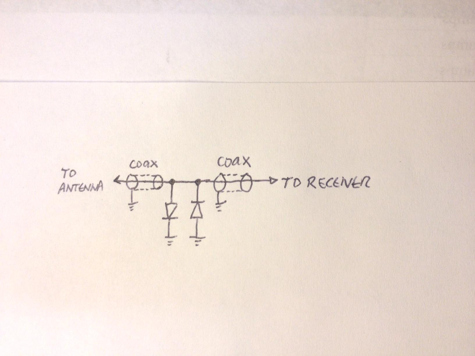
To protect a transistorized receiver, “back-to-back” silicon diodes (see schematic, Figure 5) can be connected at the receiver input between the center conductor and the shield, either connecting inside the feedline connector or added inside the receiver’s enclosure. The reverse breakdown voltage rating is of less importance. One diode conducts and limits the voltage to 0.6 V when the center conductor is driven positive, and the other conducts and limits the voltage to -0.6 V when the center conductor is negative, so the peak-to-peak AC voltage is limited to 1.2 VAC. Because the transmitter may well produce more than this voltage, there has to be some relay or other mechanism to disconnect the receiver from the transmission line during transmitting, so these diodes don’t short out the transmitter output. This type of protection has been used in some commercial and homebrew QRP transceivers to protect the receiver even from the transmitter output. (References [2] and [3] give examples.) A small signal diode, such as a 1N914 or 1N4152, will have a negligible amount of capacitance of a few picofarads and a very fast response but be able to carry a current of a few amperes for a microsecond. At the cost of a bit more parallel capacitance added to the line, a heavier power diode, such as the 1N4004 or 1N4007, can be used for the back to back diodes, with a peak current capability of more than 30 amperes. For most of the high frequency Ham bands, the added capacitance of the heavier power diode will not be noticeable to the receiver. When I tested this on 40 meters, there was absolutely no discernible loss in received signal strength. However, in my heart of hearts, I don’t trust just two diodes to protect a transistor receiver connected to a very long wire antenna from EMP. I would therefore use four diodes– two small-signal diodes like 1N914, and two heavier ones like 1N4004/ 1N4007. Additionally, I would also connect a 60-volt gas discharge surge arrestor (see next section) from the center conductor to ground as “belt and suspenders” protection for my valuable radio! In the case of a transistorized shortwave antenna with a small collapsible antenna, using two back-to-back diodes connected with short wires between the antenna (at its base) and chassis “ground” or “ground” on the internal circuit board (often a very long trace encircling the entire border of the circuit board) would probably add a large amount of protection.
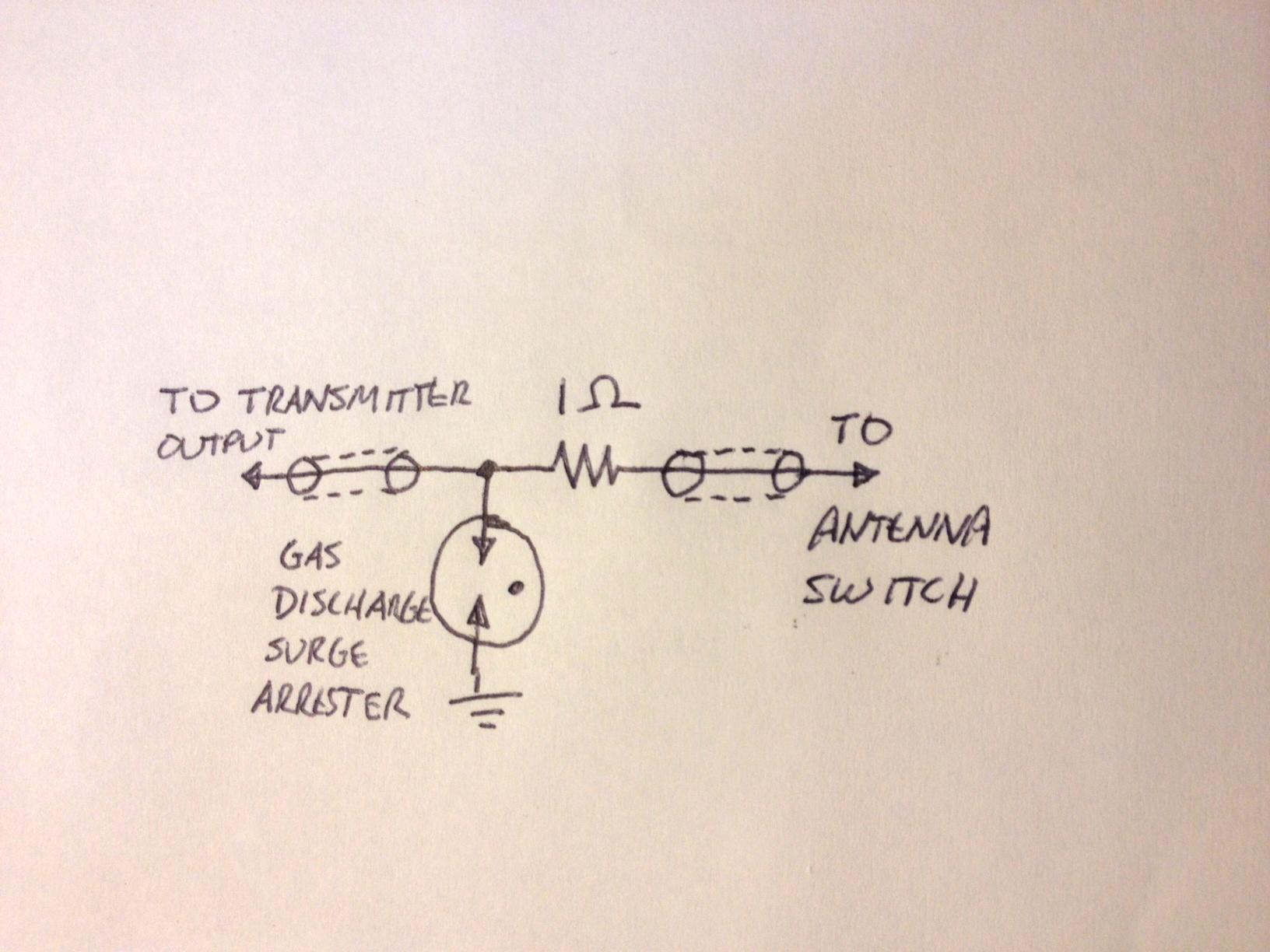
Fully protecting the antenna output of a transistorized QRP transmitter is a bit more difficult, because one must again allow passage of the normal power output voltages generated for commonly-encountered SWR ratios, yet short out voltages just higher than those to protect the transistor amplifier. If for a single instant a power amp transistor or any other within the transmitter is exposed to, say, a voltage greater than its rated Vceo or Vcbo voltage, that transistor is likely to be irreparably damaged. (It might be a good idea to stock up on some spares.) While the punch of lightning is long enough to literally melt/burn conductors and thus leave an indelible mark wherever it coursed, the E1 EMP is gone so quickly that likely only the PN junctions of semiconductors are invisibly but very effectively destroyed. Some transistor designs have relatively little margin of voltage safety. However, it is also possible that the output tuned circuit of the amplifier will screen out some of the frequency spectrum from reaching the vulnerable transistor, also. If we assume an SWR of better than 2:1 and the common 5-watt output, the output voltage is on the order of 31VAC RMS, or under 50 volts peak. One immediately thinks of using a MOV (available in all manner of voltages) to provide protection. The problem with using metal oxide varistors is that they have far larger capacitance (often THOUSANDS of picofarads) than is tolerable in the matching circuits of typical QRP HF transmitters. To get an acceptably lower capacitance requires once again using a gas discharge tube, such as the Bourns Inc. 2020-15T-C2LF. This gas discharge tube has a breakdown at 60volts (the selection of breakdown voltages for gas-discharge is somewhat more limited than for MOVs) and can shunt up to 10 kiloamperes. It is manufactured in a 3-wire version with two surge arrestors connected together. Simply connect the center wire of the pack to the transmitter output and both outer wires to the shield (ground). The capacitance is less than 1 pF; it will not affect your transmitter’s tuning, and the price is less than $3! [4] It may possibly provide adequate protection for the transistorized QRP transmitter. However, this obviously cannot be guaranteed, as we are dealing with enormous instantaneous currents. To give your gas-discharge surge arrester a fighting chance to clamp that voltage sufficiently, I suggest that you add a 1-ohm carbon or carbon-film resistor in series with the center conductor, on the antenna side of your 60-volt gas discharge surge arrestor. (See Figure 6) This can be a common 1/2 watt or 1 watt resistor, just not a wire-wound one. It will not appreciably affect your transmitted power.
CB Radios
These same solutions just described for transistorized QRP transmitters above can be applied to common transistorized CB AM transceivers. Twelve-watt single sideband transceivers with feedline SWR below 2:1 may also work well with this system.
In conclusion, for about the price of a fast food meal and a bit of wiring, one can purchase and install all the protection devices reasonably useful to protect either a QRP transistorized or higher-power vacuum tube Ham radio station, and thus have a reasonable chance of surviving a first or second strike, even while using the equipment. Equipment not in use should be disconnected from antennas; a shorting antenna switch can make this more convenient. Spare equipment should be left completely unconnected, and if economically possible, backup radios stored in a Faraday cage. As a side benefit, one gains some appreciable near-vacinity lightning protection. Power line protection from E2/E3 components of an EMP attack will be discussed in a later writing.
References
[2]An example of a QRP homebrew transceiver using back-to-back diodes to protect the receiver input. See diodes D5 and D6, which protect the receiver.
[3]An example of a commercially-available QRP transceiver using diodes to protect the receiver input. (See D4-D7).