


(Continued from Part 2.)
If a 100-watt panel is used, the voltage could be 17.5 to 19 volts at its peak amperage, which is too high for long-term operation. As tested, I use two 100-watt panels, that have one cell covered with duct tape to reduce the voltage at the pump. Voltage is confirmed using a multimeter, and output measured with a one-gallon container, and a tachometer confirms that the pump head is turning at less than 1,725 rpm. Output should be slightly less 2.50 gallons per minute (GPM) if the Dankoff Model #1303 is used, and slightly less than 1.25 GPM if the Dankoff Model #1308 is used.
2. Voltage Limited by System Design
Another technique to reduce voltage at the pump to 16vdc or less, is to use lighter gauge wire, or a long run of wire between the panel and motor, so that enough voltage is lost in the line, by design. We can use a voltage drop calculator to determine the voltage drop. Normally we would use this calculator to avoid excess line loss so that a PV system is electrically efficient. But in this situation I would use this calculation to design in a desire for voltage loss. Referring to the chart below, we see that 40 watts is required by the #1308 to lift water to a height of 20 feet and it produces 1.25 gpm. This is the math:
40 watts x 0.3 (30 percent) = 52 watts = 2.9 amps is needed.
If we have a 50 watt panel, then that would be adequate. Howevers I only have a 100 watt panel, therefore we will use a voltage drop calculator and discover that a 100 foot length of 14 ga wire will deliver 2.9 amps at just under 16vdc, namely 15.7 vdc. 12 vdc would not be too low. There is a 10.3% loss of voltage. BTW, the typical “heavy-duty” 120 Volt AC extension cord uses 14 gauge wire.
Should access to the Internet not be possible during the design process, we can download this information and print it out, as a guide and substitute for an online voltage drop calculator. We would of course use a voltmeter to confirm that our calculations are correct when the motor is under load. Here is a handy chart that can also be used to make PV systems electrically efficient.
3. Variable Resistor Method of Voltage and Speed Control
A simple do-it-yourself variable voltage resistor is almost child’s play to make. A crude example would be easy to construct and be reliable. It only requires a coil of thin gauge wire, enameled, or insulated 18 to 26ga wire in a coil. The insulation can be removed with an abrasive, or with a sharp blade, and a wiper made with narrow spring steel can be moved across the coil to increase or decrease the voltage. Look up YouTube instructional videos on “variable voltage resistor”. We can also use motor speed control from older vehicles. In high school, we made crude electric motors and controls like this.
Verifying Design Limits Are Not Exceeded, Methods of Measurement
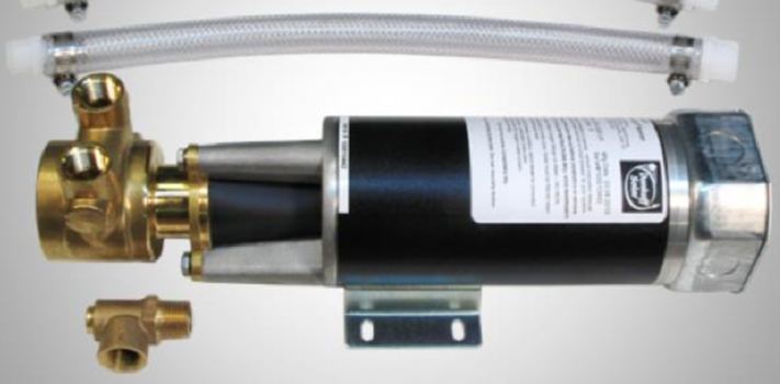
Pump output is measured with a one-gallon paint can container and a stopwatch (cell phone should offer this feature if an old-fashion wristwatch second hand is not available, or we can verbally count to 60). Motor shaft RPM can be monitored by attaching a small section of the provided reflective adhesive tape onto the coupling between the motor and pump, to “flash” at each turn of the shaft. Motor and pump shaft speed should be measured by this $14 device, or similar tachometer, available via eBay: Digital Tachometer Laser Photo Non Contact RPM Tach Meter Motor Speed Gauge.
Voltage supplied by the array when the pump is in operation should be monitored by a standard multi-meter, and measured when the pump is in operation during the peak daylight hours when the sun is highest in the sky. The maximum allowable voltage is 16vdc for a nominal 12-volt motor, and 32 vdc for a 24-volt motor. PV voltage at maximum amperage output varies by manufacture and model. Some panels deliver more voltage than others. There can be a range of 17.5 to 19 volts at maximum amperage output. Line loss can cause the voltage delivered at the pump to be closer to 16vdc, than when measured at the panel.
Simplified Monitoring
Using the chart, the tachometer, multimeter, and a one-gallon container, we can monitor the system with consistent accuracy, and determine if any of the maximum allowable limits have been exceeded. If any one of these measurements exceeds the specification limits, then reduce the voltage to the pump, as discussed. The pump can tolerate excesses, but its service life, measured in years, will be reduced.
Our primary goal should be to maximize both production and service life. For the longest service life, the pump should be run closer to 12vdc than 16vdc — or closer to 24vdc than 32vdc. The tachometer and multimeter confirmed that the pump is operated within the specification stated, but if either of these instruments are not available, if only one measurement can be taken, if the total elevation of the lift (the head) is accurately known, then the pump output in Gallons Per Minute (GPM) is by itself, an accurate indicator.
When variables such as the head are uncertain, it is best to reduce output to ensure the pump is not being operated with excessive voltages and turning the pump at excessive speed. The pump can produce more water with a pump controller, with less wattage. Array direct should however be used in low lift conditions only, and if certain techniques are used to safely operate the pump at 16 volts and less are used. The best way to assure the longest pump life is to use these powered by a small PV system.
Pump Output Chart for Low Lift Conditions and Array Direct Power Supply Specifications
Without a linear current booster (pump controller), the pump will not operate in cloudy conditions, thus the maximum gallons per day (GPD) possible can only be realized when the sun shines brightly throughout the day. Given this fact, it would be advantageous to have enough water storage for overcast days, when the pump output is low. A method to greatly increase the GPD, is to use two 100 watt panels, one pointed to the east, and the other pointed to the west. Three 100 watt panels, one oriented at the morning sun, one at the sun high in the sky when at its southernmost, and one toward the setting afternoon sky, would provide an ideal arrangement and maximum production for full sun conditions during the summer.
The following is my simplified version of the Dankoff chart that shows what is considered to be low-lift situations. Using an Array Direct with three 100 watt PV panels, with morning and afternoon orientations, as prescribed, during the mid-summer. The chart is a result of testing an Array Direct configuration in ideal conditions in peak summer, at my location that is at 48 degrees in latitude and subsequently, has long summer days. Figures are rounded. In other latitudes, and in less than ideal or average conditions, it is best to assume that production numbers will be only half of what is presented here. There can be a great deal of variation during a season. It is best to use a cistern, or other water storage method to provide water when production is less than the average water production, as is possible at your location.
| Model 1308 | Model 1303 | ||||||||
| Lift in Feet | GPD | Peak GPM* | Minimum Watts Needed | Watts Used | GPD | Peak GPM* | Minimum Watts Needed | Watts Used | |
| 20 | 700 | 1.25 | 300 | 50 | 1500 | 2.5 | 300 | 85 | |
| 40 | 700 | 1.25 | 300 | 85 | 1500 | 2.5 | 300 | 105 | |
| 60 | 680 | 1.2 | 300 | 90 | 1500 | 2.4 | 300 | 120 | |
| 80 | 680 | 1.2 | 300 | 95 | XXX | XXX | XXX | XXX | |
| 100** | 680 | 1.2 | 300 | 110 | XXX | XXX | XXX | XXX | |
| 120 | 680 | 1.2 | 300 | 120 | XXX | XXX | XXX | XXX |
Notes:
XXX = Low Lift Exceeded
**Line pressure as measured by an inline gauge was approaching 60 psi with an approximate 100-foot lift, and is the maximum pressure rating of inexpensive 1/2″ poly pipe drip irrigation line. To build in a margin of safety, I would instead use poly pipe with a 100 psi rating for lifts between 100 to 140 feet.
GPD = Average Gallons Per Day. This assumes an average run time of 5 hours per day during a growing season.
GPM = Maximum output that can be realized under ideal conditions, or during optimal solar conditions when the motor is at it’s maximum rated speed of 1,725 rpm and voltage provided is it’s maximum acceptable design limit of 16 vdc for a nominal 12 volt pump motor, and 32 vdc for a nominal 24-volt motor.
Minimum wattage for Array-Direct operation can be increased to increase the number of hours the pump will operate by orienting the panels, one mostly to the East, and the other set of panels to the West if there are two panels. For example, if the minimum wattage from the chart indicates 120 watts, as this least expensive option, then use two 100 watt panels, both oriented towards the south.
In my experience, [urchasing three 100 watt panels from Renogy, would be far less expensive than purchasing three 50 watts panels from most other sources.
(To be concluded tomorrow, in Part 5.)