


We’re continuing the instructions for motorizing a Country Living Grain Mill that can run on battery- or solar-generated power. Part 1 dealt with the full list of material and the first step, building the base board. Here, we continue with instructions.
- Create and Prepare the Motor Mounting Board. This is a critical but confusing step, so pay attention!

- Cut a 6-1/2” x 9-1/2” piece of 3/4″ plywood. The longer sides will be the front and rear. Mark one flat side as bottom. You will mount the hinge to the bottom and the motor to the top at opposite ends. Think of it as a half see-saw. The hinge will be the fulcrum and the motor will be the person sitting on one end.
- Locate the hinge mounting holes. Fold the 6” continuous hinge, and place it underneath the board along the left side. The hinge should have 1/4″ of board extending beyond either end (6” hinge and 6-1/2” board). Mark the hinge mounting holes.
- Drill the hinge mounting holes with a 1/8” pilot drill, then with a 1/4” drill. Press three of the #8 T-nuts into the top of the board.
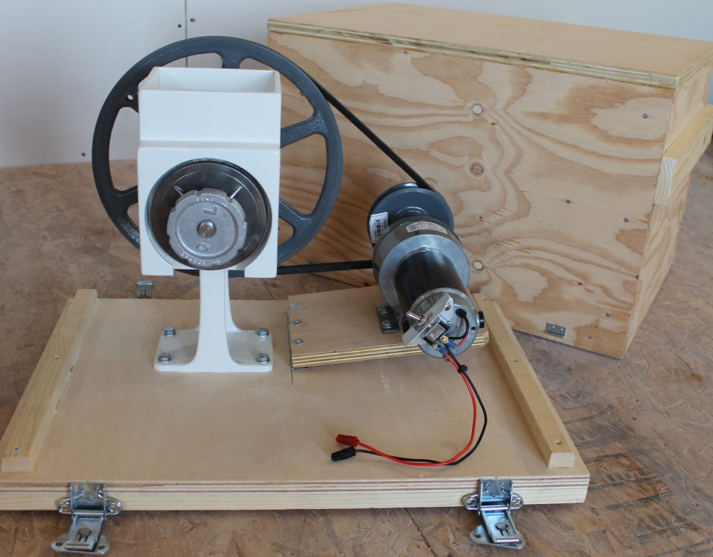
- Attach the hinge to the motor mounting board and to the base board. You will need six #8-32 x 3/4″ Flat Head Phillips Machine Screws. When finished, the motor mounting board should lay flat to the right of the mill.
- Locate the motor mounting holes. The motor mounts on the top of the mounting board, towards the right side, with the shaft and pulley end of the motor to the rear (in line with the mill pulley). The mounting holes for the integral motor mount on the Duoyou 12 volt motor are on a 4” by 1-1/2” spacing. To manually locate the bolt holes for the Duoyou 12v motor:
- Measure 4-3/4” in from the left edge, and draw a line parallel to the left edge. Now measure 8-3/4” in from the left edge, and draw another parallel line. The lines should be spaced 4” apart.
- Measure 3-3/8” in from the rear edge, and draw a line parallel to the rear edge. Now measure 4-7/8” in from the rear edge, and draw another parallel line. The lines should be spaced 1-1/2” apart.
- Verify your grid is correct by placing the Duoyou 12v motor over it. The crosses should line up with the motor mount holes. Correct any discrepancies. The exact placement of the motor on the board is not critical, but it is necessary for the motor’s pulley and the mill’s pulley to line up. Note that both pulley shafts have about 1/4″ adjustment to the front and rear for final adjustment.
- TEST FIT. If all was done correctly, the placement of the motor should be correct. However, before you drill holes for the motor, verify that the distance between the mill pulley and motor pulley will be sufficient with the following procedure:
- Use a scrap of 3/4″ wood to prop up the motor mounting board. Measure 15” in from the left side of the base board. This is where the 3/4″ scrap’s edge should be laid. Doing so will prop your motor mounting board up so that the right end is perhaps 2” above the base board.
- Slide the belt over the mill pulley. Mount the motor pulley to the motor if you have not already done so. Slide the belt over the motor pulley, and position the motor as close to your four hole marks as you can. The belt should have no slack in it, but it does not have to be taut.
- If the belt still has a lot of slack in it, you will want to mount your motor further out (to the right) on the mounting board. If the belt is too tight and you cannot get the motor to within 1/4″ of your hole marks, redraw your hole marks closer to the hinge point by as little as necessary.
- Drill the motor mounting holes with a 1/8” pilot drill, then a 5/16” drill. Place 1/4″ T-nuts on the bottom of the motor mounting board and seat them into the board using a 1/4″ bolt and washer to draw them in. Then remove the 1/4″ bolt and washer.
- Assembly
- Mount the hinge to the base board and motor mounting board, if you have not already done so.
- Mount the Duoyou 12v motor to the motor mounting board.
- Mount the Country Living Grain Mill to the base board.
- Lift the motor up so that it pivots closer to the mill, and place the v-belt over the two pulleys. As you release the motor, it will pivot down and away from the mill, thus providing sufficient belt tension.
- Wiring and Control
- Toggle Switch Mount. This method uses a piece of aluminum angle, mounted to the rear of the motor. One side of the angle is flush to the motor back; the other side provides a flat surface to mount the toggle switch. If you chose to do this, you will need a hacksaw, file and both 3/16” and 1/2″ drill bits. A toggle switch can be mounted in various locations through other means; improvise and find what works best.
- Cut a piece of 1” aluminum angle, 2” long. File or sand down any sharp edges or corners.
- On the back of the Duoyou motor, there are two Phillips screws that attach the motor to the gearbox. Remove the top screw.
- Hold the angle with one side flush to the motor back and the other side flat as a top. You may need to hacksaw or file a portion of one side of the aluminum away to accommodate the bulge on the end of the motor case. Drill a hole for the motor screw with the 3/16” bit, once you have it in a good position.
- Drill a 1/2″ hole on the top side of the aluminum angle where you wish to mount the toggle switch.
- Cut the positive (red) wire 2” or more from where it comes out of the motor. Strip, crimp, and then connect the appropriate connectors to your toggle switch.
- Zip tie the black and red wires together for strain relief (optional).
- If you chose not to use the blade-type connectors from the factory, cut them off and use whichever connectors you chose. Make certain they can handle a continuous 12+ amp load at 12 volts. This project uses Anderson PowerPole connectors to connect to a variety of wires with battery clamps, extension, solar panels, and so forth.
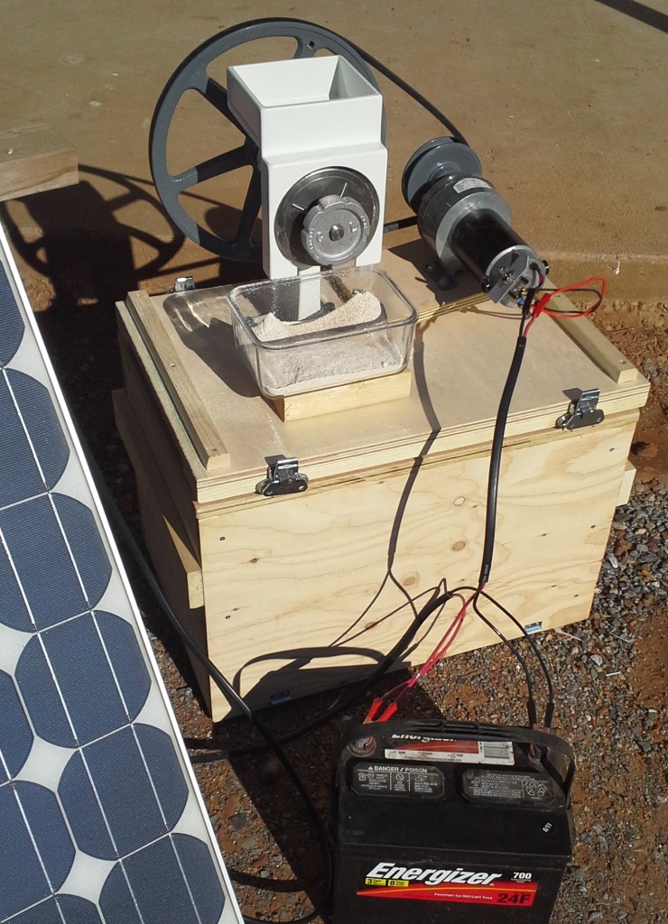
- Connect to a 12-volt power source, such as car batteries, deep cycle batteries, or directly to 12v solar panels of 150 watts or more. Fill the hopper with grain. Place a bin underneath the mill, and enjoy!
- Toggle Switch Mount. This method uses a piece of aluminum angle, mounted to the rear of the motor. One side of the angle is flush to the motor back; the other side provides a flat surface to mount the toggle switch. If you chose to do this, you will need a hacksaw, file and both 3/16” and 1/2″ drill bits. A toggle switch can be mounted in various locations through other means; improvise and find what works best.
Project 2: Instructions to build the Storage and Transportation Crate:
- Take the front and back pieces of the crate (1/2” ply measuring 15” by 24”). On what will be the inside of the crate, add the four 14” long pieces of common board (ripped to 1”). These are reinforcements for the inside of each corner. Lay them flat on the plywood. Inset them from the edges exactly the width of your end pieces (1/2”, or to be exact, 15/32”). Place one end flush with the top edge of the plywood, leaving 1” of the bottom edge protruding beyond the board. Glue, clamp, and secure each piece to the plywood with three #6×1-1/4” wood screws, started from the plywood/exterior side.
- Using your square, begin building the ends of the crate. Attach the two 15”x15” pieces of plywood to the front and back sides from the previous step. Use your square to true everything up, and then glue and screw the sides to the corner reinforcements. It may be helpful to build this over the base, using it and the pieces you added to the sides of the base as a jig, or build it upside down over the top piece, using the top to make certain everything is true.
- Once the base is complete, add the 16”x24” top of 1/2″ or 3/4″ material. Glue and screw it in place with your #6 wood screws.
- Add the two 1×3 by 16” board to either side as handles. A good placement seemed to be 4” below the top level. Use glue and wood screws to secure.
- Finally, add the butterfly latches to secure the crate to the base:
- Fit the crate over the base. If it is tight getting it on and off, you can plane or sand the inside edges of the plywood or better still, the sides of the 1×1 by 14-3/4” strips mounted on the base. Find the direction that fits best (if one fits better than the other) and label it “FRONT”.
- Take the butterfly latches and extend them. Two will mount to the front and two to the rear. Find a good distance in from each edge and height from the bottom to mount all four. For this project, the center of each latch was placed 4” in from either edge, the top of the latch mount flush with the top of the 3/4″ board. The small hooks were mounted on the crate front and back, centered 4” in from the edge and 1/2″ up from the bottom edge. Wherever you mount them, make certain when they are latched they will be drawn down or tensioned against the springs of the latch.
- Your crate is now complete! Place it over the mill and latch it down. You can use it as a seat, or set the mill on it for a table.
- Bonus – there is a lot of unused space in the top of the crate, above the motor. Use scrap wood to fabricate a storage box inside the top to store spare parts and accessories (power bar, corn auger, battery jumpers, etc.) This way you can remove the crate, flip it over and access spare parts and accessories that will always be stored with the mill.
Troubleshooting – Common Problems
- Mill turns in wrong direction. From the front position (pulley behind the mill), both motor and mill should be turning in the counter-clockwise direction. If they are not, reverse the connections going to the motor.
- Mill does not turn while using solar. While the motor is rated for 12amps at 12 volts (144 watts), I have found when using only 150 watts of old solar panels the motor bogs down at fine grinds. Back the grind off a little bit and try again. Make certain your panels are positioned to create maximum power. If this continues happening, consider upping your solar wattage or adding a battery to the system.
Conclusion
You should now have a robust, motorized mill. It is easily transportable, allowing you to mill outside, close to solar generation and keep the mess outside, or take it on the road to use elsewhere. In storage it will be well protected; in milling your manpower will be free for other tasks, and your family will benefit from fresh flour and wholesome bread
I’ve also provided a pdf of the Grain Mill Drawings. Enjoy!