


(Continued from Part 1.)
Transceiver Selection
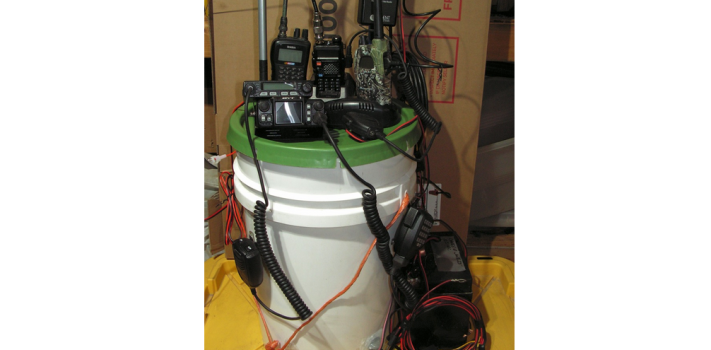
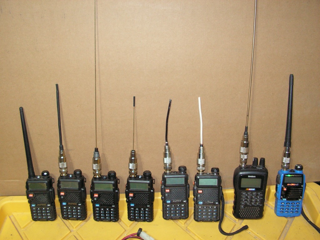
 These are various sizes and types of radios. For the purpose of size comparison, the photo illustrates why we should choose the smaller-size transceivers that will allow one to pack as many as possible into the metal can that is housed inside the 6-gallon bucket. The metal can is needed for protection from EMP, and as an additional protection from the environment when stored inside, or outside the bucket.)
The smallest in size is the tiny Anytone Smart which is a 10 Meter FM, and 16-watt PEP CB AM/FM that has 400 channelized frequencies between 24 to 30Mhz. It covers 10, 11 and 12 Meter and CB services in foreign countries if the owner performs two modifications. Unmodified, it is a 10 Meter AM/FM that might be of just limited utility. It does not have SSB, but it is inexpensive. A small-in-size and inexpensive (less than $100) Uniden CB would be a better choice for most. While there are better CBs, the smaller size transceivers makes room for other important equipment. The lower-in-cost CBs should transmit with the same amount of power as the most expensive mobile CBs.
Each of the two 25-foot coaxial cables can be put into a tree, or on a pole and attached to several 1/2 wave dipoles antennas for CB, 10 Meter, VHF, or UHF 1/4 wave ground plane wire antennas. The other mobile transceiver transmits with a maximum of 45 watts, however, it is relatively large and only covers VHF. The largest 1/4 wave ground plane antenna is for 70cm. 1.25CM and 2 Meter/MURS are dipoles.
If there is not enough space available in a small metal can for all of these transceivers, several Baofeng UV5Rs would have to do the job. As the Baofeng UV5R and other similar transceivers, such as Anytone, Wouxon, and others are usually dual banded, a handheld can fill the roll of a mobile in a low power operation when connected to an external antenna as it’s ability to send and receive signals is improved by 7.7dBi (about 2 times better). The Midland GXT GMRS/FRS is a good choice, because of the very low power setting that transmits with no more than 200 Mw (2/10th’s of one watt). These can be used with the simplex repeater as well.
 The other is an older Smart Comm, a VHF business band handheld transceiver. Although of good quality, the battery replacement cost and availability for older good quality transceivers using ni-cad, or nickel metal hybrid batteries can be an issue due to their age and cost, and these take up more space than the Baofeng UV5R, and other choices. The bucket could be in storage for a considerable of amount of time, therefore lithium and AGM battery technology are the best options if periodic maintenance will not be possible.
Satisfying Operational Requirements
If for teh sake of redundancy we can not afford several Yaesu 817s, or ICOM 705s, the job can still get done. The featured transceivers do cover most of the UHF/VHF spectrum. The notable exception is HF and low VHF that, with exception of Citizen Band, are Amateur Radio bands. 6 meter would be nice, but we do have the 16 watt PEP Anytone Smart that has a slice of 10 meter (AM/FM only) that goes beyond what common and inexpensive transceivers can do. The FM part of the CB also gets us off the well-beaten path, and is mostly unintelligible to the AM part of the CB. A CB transceiver is a must-have, because it is the easiest to use, and therefore will be the radio service most will use for longer ranges. Technician class licensees can leave the Anytone Smart unmodified, and use the 10 Meter as is, and purchase a CB. The Anytone Smart is an oddball, yet it is only $59.00. It is not a must-have like the CB. The QYT KT7900D was only $109, so for about $168, it is a lot capability for the money spent.
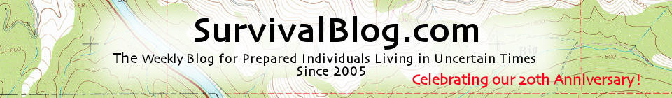
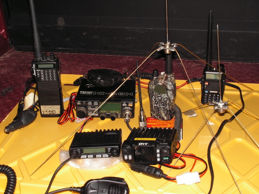
When used in the field, to reduce the clutter on a makeshift desktop, two of the transceivers pictured can be operational and protected inside the bucket, or the metal can, the Baofeng that is used exclusively for digital transmissions via an Android tablet, and the transceiver that is apart of the simplex repeater. An external microphone (such as a lapel mic) can also be connected to a Baofeng that is secured by its charging base, and stationary. The top surface of the metal can offers additional working space.
Antennas
Because space is at a premium in the Commo Bucket, compact homemade antennas were used. Most commercially made antennas will not fit inside the bucket when fully packed. Learn how to make simple dipole antennas that are compact enough to fit into a pack, or Commo Bucket. Constructing these now will be the basis for larger and better antennas in the future. And learn field expedient techniques that can keep you on air.
The ability to make one’s own antennas for their handhelds and more powerful base station transceivers that are resonant on the same frequencies is an essential skill needed to maintain the station. It is also an opportunity to get off the beaten path, and add a layer of communication security via obscurity. In the section about making handheld antennas, and other items in this article, I am not aware of any source that provides this information. This means the reader will have in their possession a technical advantage that few others have. Staying ahead of the rest is an important advantage. Always adapting, and innovating means we have a better chance of surviving. Those who refuse to adapt, perish.
Good antennas can be made with only a multi-tool, a soldering gun, and an SWR Meter. A SWR meter would be difficult to find after a collapse. Because most can not afford to buy multiple units of antenna analyzers, so several SWR Meters will have to do. Antennas are the other half of what make a transceiver work. A low-quality, inexpensive transceiver on a good antenna will outperform the highest-quality transceiver that is connected to a low quality, or damaged antenna that we are unable to fix. Using a damaged antenna that has an excessive SWR, will eventually damage the transceiver. Get multiple sets of these tools. Invest in several SWR meters first, and a supply of solder, flux, and several soldering irons or ‘guns’ as well.
Rugged DIY Replacement Antennas for Hand Held Transceivers
In recent months I tested the antennas in a new lot of Baofengs, and found 20 percent to have excessively high SWRs. Baofengs do not automatically turn the power down protect itself from excessively high SWRs. Because of the inconsistent performance of Baofeng and Nagoya antennas, for the VHF side, I’be replaced them with reasonably priced Wouxun antennas that are ideal for 150 to 155Mhz. The closer in length that the antenna is to it’s physical 1/4 wavelength, the better a radiator it is. An excessively high SWR on a longer antenna usually propagates better than a shorter antenna with a low SWR. This fact leads the user to believe that the longer antenna is a better antenna, when in actuality, damage to the transceivers finals is occurring. My homemade UHF handheld antennas have a very flat SWR, and propagates as well as the Nagoya.
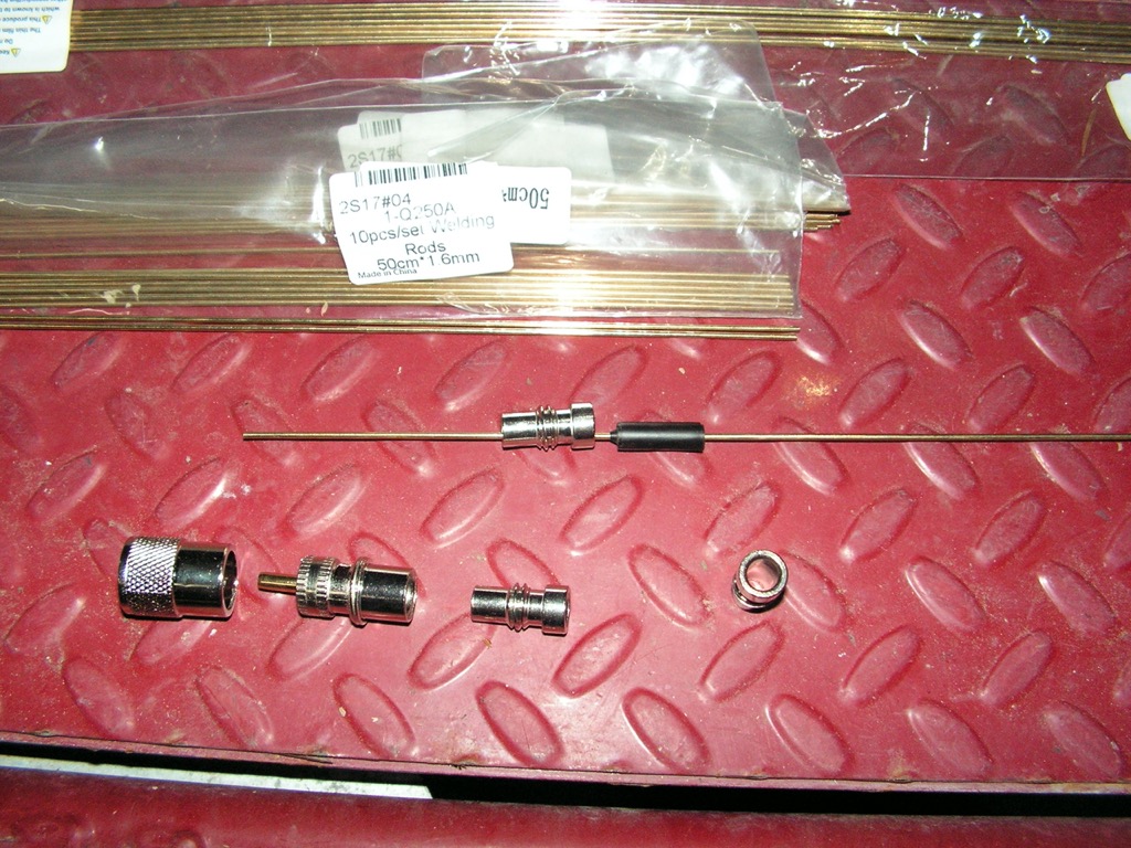
The flexible version uses Tram RG8X coaxial cable. The other version uses thin low-temperature bronze welding rod that is flexible as well. RG59, and RG58 would work, but the thin and brittle center conductor makes it a distant second choice to the stranded RG8X center conductor. RG8x is well worth the expense. The quality of RG58 is now inconsistent and often disappointing. Order a spool of 500 feet of Tram RG8X for a lower-cost supply of good cable ($221.00). For each antenna, we will needed one SO239 (UHF) to SMA Female adapter, one PL259 connect, and 6 inches of cable. Simply attach a PLAYS coaxial cable end to a cable that is 6 inches long. At the connector, remove the braided outer shield to expose the insulated center wire that will be a radiator.
Because the UHF antennas are broad-banded (50 megahertz of coverage), an SWR meter is not necessary if one knows the length of the radiator for a particular center, or ‘design’ frequency. For the RG8X cable. pt bronze wire antenna, cut the center conductor to 4 3/4″ for 420.000Mhz to 460.000Mhz. For 430.000Mhz to 480.000Mhz cut to 4 1/2″. For GMRS, 462 to 468Mhz, cut to 4 5/16″ for a < 1.1:1 SWR at 465.000Mhz. The wire type is easiest to construct. Darken the center conducting wire’s white insulation with a black permanent marker, or add a section of heat shrink tubing over the length of the radiator to stiffen it, and to improve its appearance. This kind of antenna works well on UHF, but for 1.25CM, use the bronze welding rod, or stainless steel whip. This antenna design does not work on 2 Meter or MURS frequencies without a counterpoise. The cost is less than $4 each in parts, and the performance is excellent. The actual price in parts might be around $1.50, if the SO239 to SMA F adapter is also used for connecting to an externally located antenna. And the radiator can easily be soldered and replaced by a longer one that can be tuned to a different part of the spectrum.
Quarter Wave Ground Plane Antennas
A taller pole can also be fitted inside the blue in color pipe that is attached to the side of the bucket to raise the height of the antenna. The saying in the Amateur Radio world, that ‘height is might’ is a well-proven rule of thumb. A height of 15 feet provides the most coverage for the least height. The heavy weight of the storage battery inside can acts as ballast that stabilize the weight of a VHF yagi or larger VHF J-pole. We could also pile a few heavy rocks on the top of the bucket.A 1/4-wave ground plane is a common antenna design does well in all situations that also has a broadband width, typically 10 megahertz or more. Because of these attributes, it is the most popular antenna type. This version is quick and easy to fabricate with a soldering iron, and a propane torch that allows a generous of amount of solder be applied to solidly affixed the ground plane radials to the SO239 panel connector.
With practice, construction time requires only 15 minutes. Tuning is easy. Other fabrication methods also work, but soldering is a the more mechanically and electrically sound method. Use 1.6mm x 50cm low-temperature bronze welding rods, and SO239 panel connectors. Stock in quantity to produce antennas of many kinds.
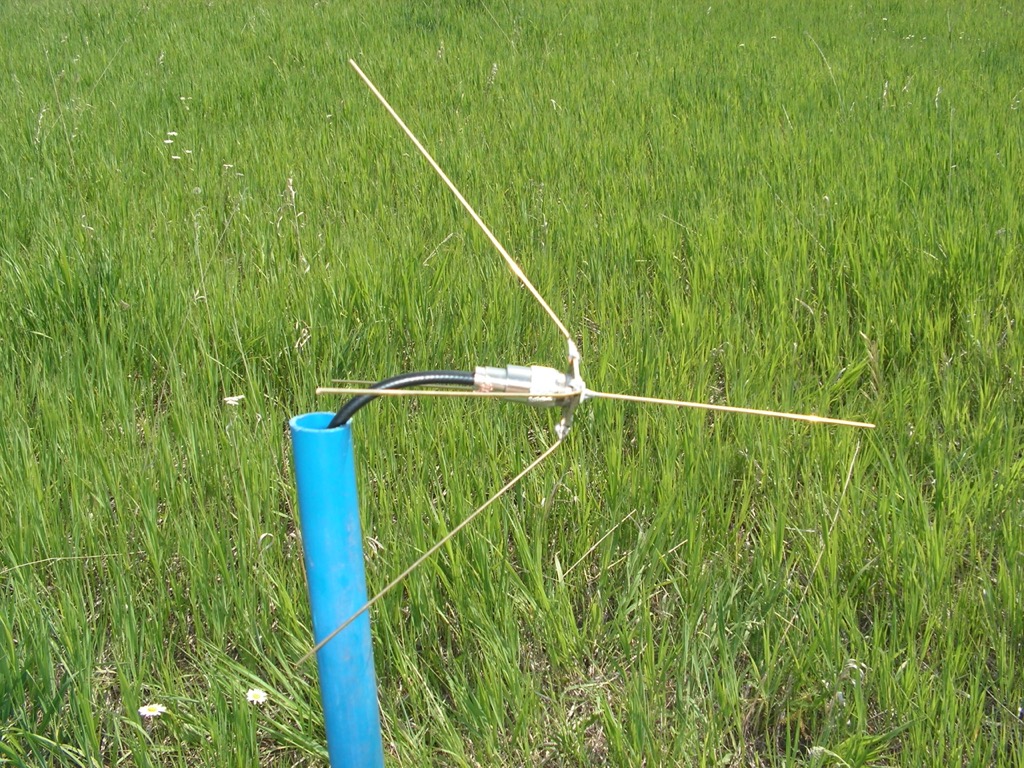
The Horizontally or Vertically Polarized Dipole
 Using a horizontally polarized antenna decreases the ability to be received by a vertically polarized antenna typically used by an intercept station. Attenuation is between 10 and 20 Dbd. This antenna, when horizontally polarized is a bidirectional antenna. Point the ends of this antenna in the direction that we would wish the signal would not go, and attenuation in that direction will be greatest, and closer to 20Dbd.
Constructed with 10 AWG solid copper wire, and a common PL259 connector instead of the SO239 panel connector, this antenna can be made compact by folding, or rolling up the elements. The elements of this particular antenna are stiff enough to support its own weight and shape when deployed horizontally. A VHF dipole is 72 ohm antenna, so there is an impedance mismatch and penalty, yet this VHF dipole can easily be tuned to cover 144Mhz to 155Mhz. There is negative gain relative to a 1/4 wave ground plane antenna, yet that is acceptable in a low-powered net where we would strive to limit propagation by the use of low power. An air choke type balun is used to keep RF from coupling with the outer shield of the coaxial cable to prevent changes in the SWR should the antenna not be installed correctly. An air choke is not absolutely necessary if the cable is run perpendicular to the radials for one 1/2 wavelength in distance. It is shown in a vertical polarized position, and can easily be hoisted up into a tree. Use in this way, an ‘air choke’ type balun is necessary.
All horizontally polarized antennas, be it a dipole, j-pole, yagi, or Moxon antenna can suffer from RF reflecting off of the ground, particularly moist ground, and should be elevated at least 3 wavelengths in height to avoid interference with the ground, should it be moist. Moist ground reflects RF if the height of the horizontally polarized antenna is at a certain distance from the ground, and this can cause excessive SWR. It is best to install a horizontally polarized antenna using an SWR meter to determine the necessary height in local terrain. Dry, sandy ground is less of a problem than moist loamy soils.
Horizontally polarized UHF antennas have physical wavelengths that are one-third the length of VHF, about 27 inches (at 420Mhz) long, and therefore can be used as a horizontally polarized antenna at a height of 80 inches, or 7 feet, or higher. The physical wavelength of VHF frequencies that we would use are 84 inches (at 144 Mhz) or shorter, and would require a minimum height of 252 inches, or 21 feet. Therefore, UHF is more suitable for hasty deployments, and in LPOPs that are necessarily concealed, and close to the ground. UHF antennas are physically compact, and are more convenient to carry and use. This is an important consideration where horizontally or vertically polarized directional antennas need to be employed. And UHF does not scatter as much as VHF, and propagation from a UHF directional antenna is less likely to be reflected, or refracted over terrain, and deviates less from the intended bearing. UHF is easier to limit with foliage, and therefore terrain masking can be more effective. It is also easier to find quieter sections within the band, and the shorter wave length can propagate adequately well enough for most Areas of Operation (AOs).
The Emergency Dipole Antenna
It is possible to break, or be necessary to abandon antennas, therefore we should have an ability to make an emergency antenna. The dipole is the best choice for such an occasion.
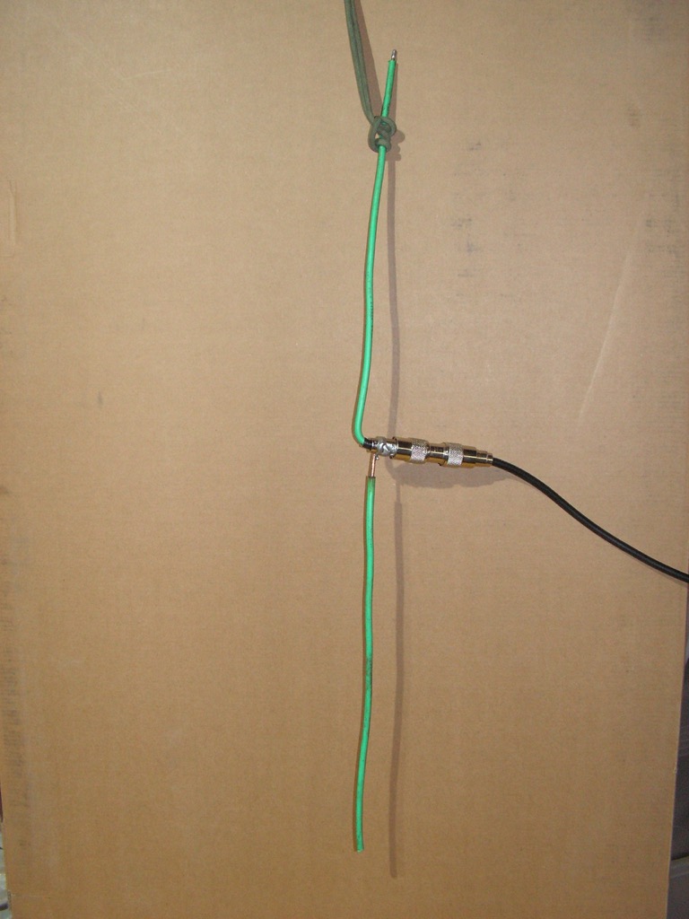
 If in the field with only cable, cordage, and a multi-tool, a field expedient antenna can be quickly constructed. As a test of my own skill, and having memorized the length of a quarter wave ground plane antenna for GMRS, that is 6 inches, 6 1/8″ was chosen to get the antenna to work the repeaters in the top part of the 70CM band. The center wire of the coaxial cable was separated from the outer braiding, and cut to 6 1/8″. The outer shield was used as the counter poise to make the dipole complete, and cut to 6 1/2 inches. An air choke was held in place with twine. The air choke prevents RF from coupling with the rest of the cable, and can lower the SWR when the antenna is hoisted up high, and in a less than optimal position. Cordage was tied to the end of the radiator to suspended the antenna. The SWR was less than 2.0:1 from 425 to 455Mhz, and 2.5:1 at 462.000Mhz, 2.0:1 at 463.000Mhz, 1.2:1 at 465.000Mhz (the center frequency), and 2.5:1 at 468.000Mhz. This would be a respectable emergency antenna, one that can work almost all of the 70CM Amateur Band, and GMRS.
The Compact and Rugged UHF Moxon Antenna
 The Moxon antenna shown is designed for GMRS fits inside a fully packed bucket is shown alongside a yagi made for GMRS that is also featured in the article. This yagi, although it can be made to be compact, is too large to fit into the bucket. If the yagi were made of PVC pipe, sections could be disassembled.)
The rectangular-shaped Moxon antenna is a directional antenna that casts a broad RF foot print of 110 degrees. It has a modest gain of around 6Dbi. It magnifies a received signal about 2 times. 1 watt from a Baofeng would come out of the Moxon as 2 watts ERP (Estimated Radiated Power), and 20 watts of power out of a QYT KT7900D would leave the antenna as 40 watts (ERP). This reduces the demand on a a power supply as well as improves COMSEC. It has an high front to back ratio of 30Dbd, and a sharp null that makes finding a rough bearing possible when listening to the receiver, or by using the signal strength meter on the QYT KT7900D transceiver. It is conveniently located on the bucket making it possible to rotate this directional antenna while observing the changes in the strength meter, or the volume and clarity of the audio received. If the signal is strong, use the Moxon horizontally polarized to attenuate the incoming signal, and the null to the rear will more accurately indicate a line of bearing. A yagi designed to transmit on a particular range of frequencies, UHF/VHF, would be a better tool for this work. This Moxon is good for common FRS/GMRS, and 70cm.
The Tape Measure Yagi is designed 2-Meter and RDF work.
A Compact DIY Yagi for GMRS
This was made in about an hour with $5 dollars worth of materials. The boom is as short as it can be, 21 inches long, so that the elements can be turned to be inline with the boom, and be protected during transport. It is too large to fit inside the bucket, yet it is compact and rugged enough to be carried. It tuned up up nicely < 1.6:1 between 462 to 468Mhz, and is 1.1:1 at the center frequency of 465Mhz. There are commercially made yagis that can be disassembled for carry. The gain is about 7dBi.It is based upon my design in a previous article, but using 1.5mm bronze welding wire instead of 6 to 12mm elements. Because narrow gauge wire is used, the bandwidth is not nearly as broad, but it is still plenty wide enough for GMRS. The length of the elements are shorter than those detailed in the article:
Building a EWB/UHF Yagi – Part 2, by Tunnel Rabbit
Field Expedient PL259 Connectors Repairs
 The key steps are illustrated in the photographs. When purchasing solder wire, choose 0.8mm wire as it can be used for all soldered connections as well as field expedient methods. Shown are the techniques that make soldering a PL259 with a common lighter possible. Note that the center wire is wrapped with 0.8mm solder wire. 4 short sections of this solder wire can be inserted into the plug end prior to heating to fill the plug end with solder when heated. Duct tape is used as a replacement for a missing collar for RG8X coaxial cable. The connector threads onto the duct tape, and over the outer shield, and therefore does not need to be soldered.)
 As an emergency repair, this field expedient method works best with RG8X coaxial cable in the event that a PL259 connector is not available. The transceiver is a Yaesu 2600M.
Tuning Antennas
In essence, all antennas are a form of a dipole antenna. A dipole antenna is the easiest to make and tune, and can be made to be rugged. Because of the broad bandwidth of dipoles, and 1/4 wave ground plane antennas (The Jungle Antenna), in the event that a new antenna needs to be constructed, use the formula 234 divided by the frequency in megahertz times 12 to obtain the length of the elements in inches. Make the calculation for a frequency that is in the center of the frequency range to be worked. Add 5% in length to the ground element or radials, and add a 1/2 inch to the radiating element. Using an SWR meter, transmit on the frequency that is in the center of the desired range. To tune, equally and incrementally reduce the length of the radiator, and the radial(s), by no more than 1/8th inch or less, until the SWR is at it’s lowest point, as close to an SWR of 1.1:1 as possible. The frequencies on the extreme low and high of the center frequency should be less than 2.0:1 if using a good quality SWR meter.
If the meter has not been proven to be accurate by validating its readings against another meter, then an SWR of less than 1.5:1 is a better rule of thumb. Modern SWR meters can be more accurate than the meters produced in the past, yet because of the inconsistent quality of products now made in Asia, check the meter with another meter to be certain of its accuracy. Because the quality of inexpensive meters is inconsistent, I can not recommend any inexpensive SWR meters.)
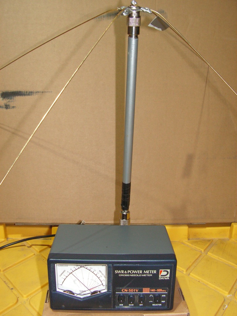
The QYT KT9000D Transceiver and a Custom Made Antenna Mast
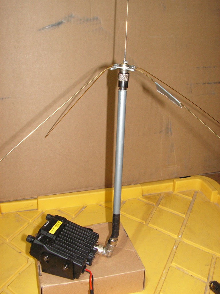 With this mast, stealthier deployment in a hide is possible. The previous photo shows the mast and antenna as tested together by a SWR meter. The SWR is a low 1.1:1, and flat. The mast in no way affects the performance of the antenna.)
(To be continued tomorrow, in Part 3.)