


(Continued from Part 3.)
Crossband Repeaters
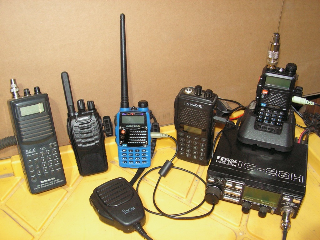
The Anytone AT5888uv, or the TYT TH-UV8000, a 10-watt handheld ($79) are examples of what I prefer in a open-banded transceiver with a crossband repeater. These use only one dual-band antenna, and are true two-way cross-band repeaters. For low-power operations, the TYT TH-UV8000 is the most practical. The Anytone AT5888 moblie with 50 watts of power, can do the same job and be a base station transceiver, yet it would draw more power, and when in use as a repeater, it can not be a base station transceiver. So, get both!
The One Way Cross Band Repeater
 As a replacement for a Baofeng UV5R that acts as a receiver, these transceivers work well in a DIY cross-band repeater with a Baofeng UV5R on the transmit side. A Baofeng-to-Baofeng transceiver cross band repeater has its advantages in terms of flexibility, and in terms of a logistical advantage as these low-cost transceivers can be stockpiled, and making a patch cable from audio cable purchased at yard sales or thrift store is possible. This patch cable has a 2.5mm plug to a 3.5mm plug that when connecting two Baofeng, or other transceivers together, makes a UHF/VHF one-way crossband repeater. If we use two one-way cross-band repeaters together, we would then have a two-way repeater that can operate in a split-frequency communications circuit.
Using two Baofengs or other similar transceivers in a one-way cross-band repeater has certain heretofore unexplored advantages, capabilities not found in commercial cross-band repeaters. For example, we can cross-band repeat from 1.25 cm to UHF, or from 2 Meter or MURS to 1.25cm. Although 1.25cm is VHF, it is not related to 2 meter, or MURS harmonically. Using a scanner that receives CB frequencies, we can cross band repeat from CB, (11 meter), to upper VHF, and UHF frequencies that the Baofeng can transmit on. A reply from the receiving station can be sent using a second crossband repeater that allows us to use different frequencies. We would then have, for a lack of a better term, a ‘multi-split frequency circuit’. Be careful not to use a combination of frequencies where the harmonic counterpart creates a positive feedback loop. Divide the lower frequency on the transmit side by 3 to determine if the harmonic frequency is close to the frequency the receiver is set on.
We can use split frequencies, and combinations of various techniques, in an endless combinations in succession, tactics that Sun Tzu would recommend. Using directional antennas will add to an ability to confound and confuse interceptors. We’ve gotta keep them guessing and off balance. We should also continually change our methods, call signs, commo windows, brevity codes, etc. Routine would be a death trap.
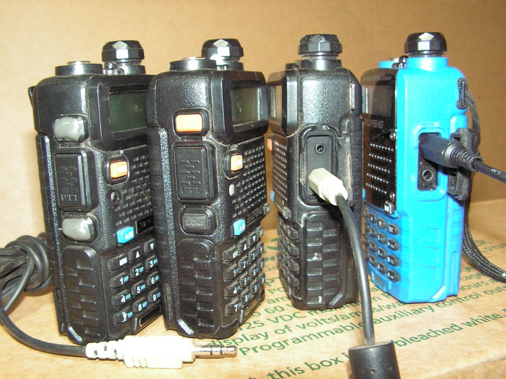 This photo shows the location of the patch cable connection between Baofeng UV5R transceivers. The lighter-in-color plug is a 3.5mm plug that is inserted into the receptacle labeled ‘speaker’, and the black-in-color plug is a 2.5mm plug inserted in the receptacle labeled ‘microphone’ on the blue-colored Baofeng. The other pair of Baofengs show where to apply an epoxy to disable the flashlight and monitor functions. The monitor button should not however be disabled as this feature allows us to open the squelch in order to hear a very weak signal. The UV5R’s built-in flashlight can also be disabled with black color nail polish.
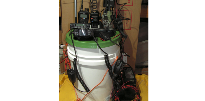
The Two Way Cross Band Repeater Box
The box is connected to two Baofeng UV5R transceivers with a two-pronged plug ends that are the same as the programming cable. This makes a two-way repeater that is operated in a similar way that a duplex Amateur repeater does, where the transmit frequency is different than the receive frequency, either higher (UHF) or lower (VHF). It is different from the typical way a duplex repeat is operated in that we do not use for example, a .600mhz step up or down for 2-meters. This is the least costly way to make a cross-band repeater, but we still use two antennas and separate cables and must be able to place these antennas away from each other as I will discuss. The additional cost of materials to use this type, makes the cost of a TYT TH-UV8000, justified.
Antennas for Cross-Band Repeaters
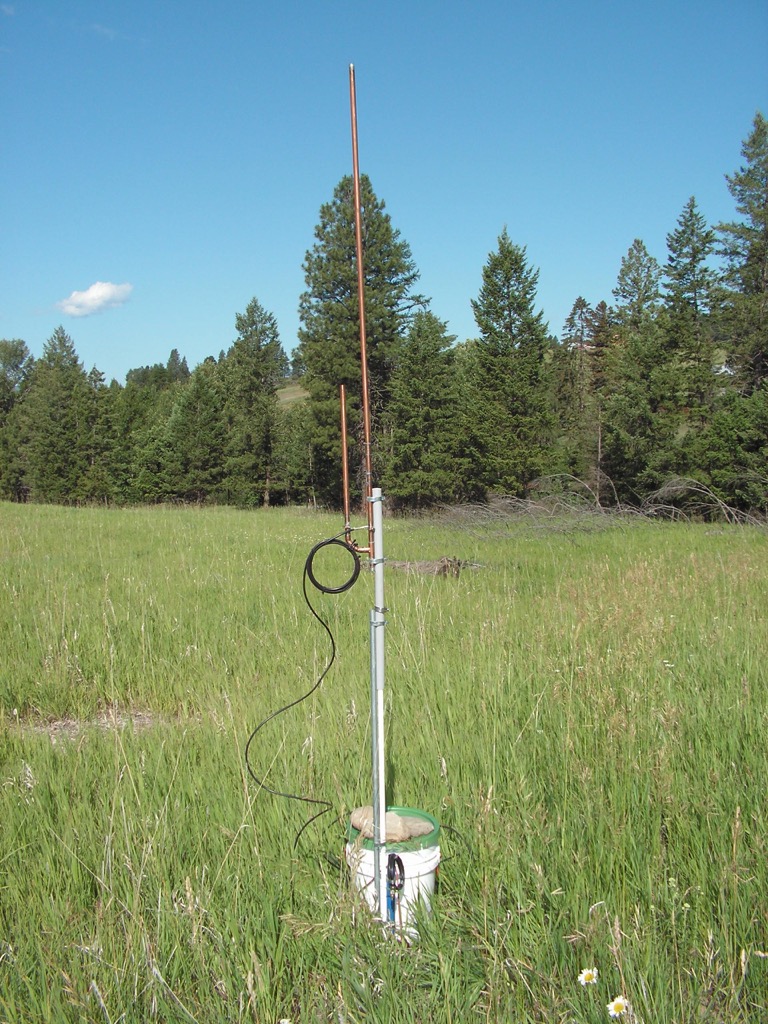
Here is an example of a dual-banded J-pole tuned with a center frequency of 153.000Mhz and 465.000 (MURS and GMRS). It is an omnidirectional antenna that is attached to the bucket in the photo. The same J-pole can be made for 2 Meters and 70cm. I make my own. They are hard to break and propagate well. It would be all that is needed for commercial cross-band repeater such as the Anytone AT5888uv (50 watt maximum), or the TYT TH-UV8000, a 10-watt handheld ($79). The J-pole would receive much better than a UHF antenna that is inside the bucket. All of the antennas featured in the photos are my home-built and tested antennas. I suspect that commercially made J-poles are similar to mine in performance. I can recommend KB9VBR’s Slim Jim and J-pole antennas.
The Dual Banded Moxon Antenna
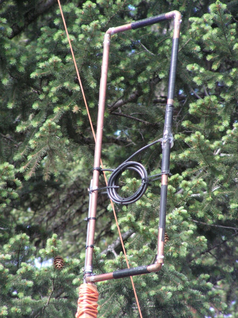 This is a dual-banded directional and omnidirectional Moxon antenna that transmits and receives on VHF (MURS and 2 Meter) as a directional antenna, but transmits and receives on UHF (GMRS) as an omnidirectional antenna. It can be used in an unusual application with a cross-band repeater.) This home-built dual-banded Moxon antenna with a center frequency of 153.000Mhz. It is a high gain (6dBi) directional antenna when transmitting on VHF, and an omnidirectional antenna on UHF (GMRS). This means it will receive and transmit GMRS as an omnidirectional antenna, but receive and transmit on VHF as a directional antenna. After line loss is considered, it will double the power out on the transmit side of a cross-band repeater.
This antenna could have an unusual application where low-power handhelds transmit into a cross-band repeater connected to this dual-banded Moxon antenna. The Moxon can receive on UHF from any direction, and the cross band repeater sends the signal out on VHF on the same antenna that then acts as a directional antenna. Ideally, the distance base station would be using a VHF directional antenna and low power to respond. This would add a layer of COMSEC as we are using directional antennas on both ends of the communications circuit are more difficult to intercept and more difficult to Radio Direction Find (RDF).
Antenna Placement for Cross Band Repeaters
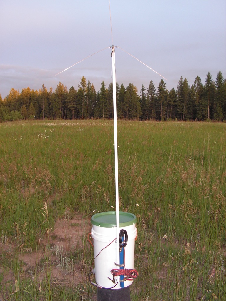 In a confined space, or mounted on the bucket for use with a cross-band repeater that uses two transceivers, antenna placement must be done correctly. A taller pole can be fitted inside, or attached to the blue in color pipe that is secured to the side of the bucket to raise the height of the antenna. The top section of the blue pipe/antenna pole can be detached and placed inside the bucket for storage. A second and longer pole can be made from PVC, and cut into 5 lengths of 10 inches each with couplings, and stored in the bucket. Or we could use a pole cut from a tree branch that raises the antenna 42 inches or higher above the bucket lid. The actual or physical wavelength is 82″. A half-wavelength is 41″. All frequencies above 144 Mhz will have a shorter physical wavelength. In this way, the antennas will not become electrically coupled, and cause excessive SWR, or distort the radiated pattern of the transmitting antenna (2-Meter). The farther away the antennas are, in terms of either or both, height and distance, the better.
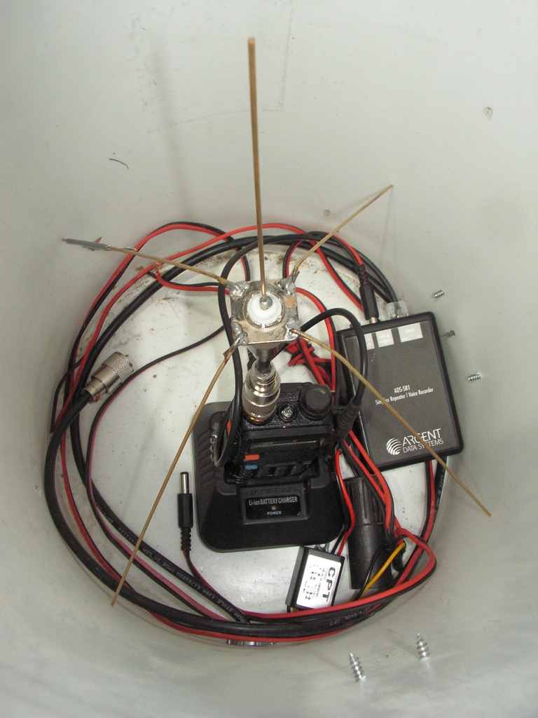 This is the inside of the bucket that would be the location of the receiving UHF antenna for a crossband repeater, and the location of the antenna for the simplex repeater. In different circumstances, the blue mast attached to the bucket could also be used. The Baofeng UV5R has a homemade 1/4-wave ground plane antenna attached using a very short section of cable less than 2 inches in length. This short cable can be replaced with the use of a PL259 to PL259 adapter. The antenna is superior in performance to any commercial antenna designed for handheld transceivers, and the radials keep the transceiver centered and upright during transit.)
(To be concluded tomorrow, in Part 5.)