


Like many preppers, I have a safe with a digital lock that I purchased before I understood EMP, and I would now like to have some protection for that lock against the E1 component of an EMP attack. (Because the lock is not attached to any very long wires, the E3 component is not an issue.) I present here a simple technique that may provide significant (although imperfect) protection and which is amenable to becoming a commercial product by a motivated individual (and I freely give away the idea). Such additional protection would be expected to raise the probability that I won’t have to hack into my own safe after an EMP event.
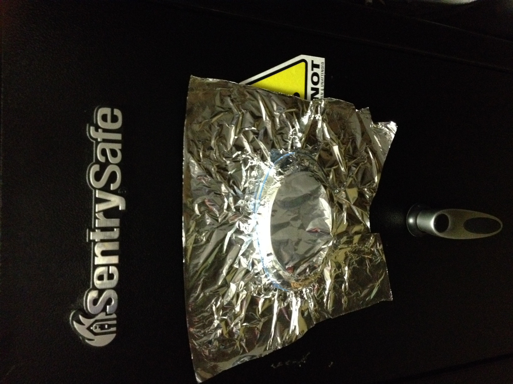
The accompanying photo shows a swath of household aluminum foil simply pressed over my digital lock and held in place with a rubber band. The outer portions are hand-pressed to lay as flat as possible against the painted surface of the metal safe door. If you are careful, you can remove and re-install it several times. A bit of structure provided by some masking tape around the lock would probably make it last even longer. As I will demonstrate both by theory and experiment, even this simple system is likely to be of significant help, increasing the probability that your lock will not be harmed. Also, it could very easily be manufactured and a far better version sold at a profit by an enterprising person. Create a steel mold a bit larger than the typical electronic lock by grinding away at a slice of a steel rod. Take 1/16″ aluminum or steel and hammer it to fit over the mold (the “bubble”) to have a fairly flat circular “brim” around the “bubble” that can lay flat against the safe front. Add a bit of the thinnest Velcro fabric you can find to secure it to the safe (possibly even indenting a spot or two in the “brim” so the “hat” will lay as flat as possible to the safe. It’s done. Now, market it!
Because electronic locks may be relatively small with short wires, presenting a small “aperture” to receive E1 energy, some may actually already be relatively resistant to EMP. There are commercial locks available for under $200 that have been shown to be unaffected by “simulated EMP”[1]. However, my particular low-end lock hasn’t been tested to my knowledge, and there would be a gunsmith charge on top of the purchase price to put a tested lock in place. That would raise the total cost beyond my mid-range safe’s value. Hence, I pursued this attempt to protect my existing lock. (In case you’re wondering, yes, I have the ability to break into that safe.)
If you aren’t interested in a lot of electrical engineering discussion, immediately skip down to the last section on experimental confirmation.
What is the electromagnetic threat signature of the E1 attack? The milspec “test” waveform (See Figure 1 of Ref. [1] ) that is used to simulate an E1 (hopefully similar to the real thing!) is a very rapidly rising and falling pulse (a few nanoseconds) creating a very high voltage/field, which has a frequency spectrum that is fairly constant (and large) from very low frequencies, up to about 10 MHz, and then declines as it moves from there higher. (See Figure 2-15 of Reference [2]). At 1 GHz the simulated spectrum is three orders of magnitude weaker than it is at 10 MHz, which would suggest that the primary goal should be to protect against “short wave” frequencies and lower. Note, however, that the actual observed signal (See Figure 3-1 in Reference [2]) has many very fast “ripples” and therefore may have more potent microwave energy than the simulation test signal; so, good microwave protection may also be important. As I will attempt to argue, my suggested solution probably provides significant (but not total) protection at these frequencies of interest.
To actually calculate the resulting electromagnetic field versus time, or measure the exact protection such a device would provide to my electronic lock would be quite a computer or measurement feat. (Hint: This would be a great thesis for a Masters’ student in Electrical Engineering.) However, one of the things I learned during my training in electromagnetics and electrical engineering was to hunt for similar problems that did have a known solution. In this case, the “brim” of the cover, together with the steel door of the safe, acts like a very thin waveguide for the transmission of electromagnetic waves. This effective waveguide has “defective ends” because it never makes connection laterally to the safe door but to very small wavelength (high microwave) signals, and it resembles an infinitely wide but not very tall (about 1/8″) waveguide. Also, when looked at from the lower-frequency circuit designers’ viewpoint, if the entire system is about 12″ in diameter with a 6″ diameter central bubble, the brim has a surface area of about 85 square inches approximately 1/8″ or less from the safe door, and therefore has roughly a capacitance of >150 picofarads, representing an impedance of about a thousand ohms at 1 MHz and 10 ohms at 100 MHz, 1 ohm at 1 Ghz. That’s not a really low impedance but not an open circuit either; it helps to make the shielding effect better at higher frequencies in the circuit designer’s view.
Let’s further examine the waveguide analogy to the brim. Waveguides are widely used to transport electromagnetic energy from transmitters to antennae. However, they are usually used only for microwave (>1 Ghz) signals, because of the problem of “waveguide beyond cutoff.” That is, if the dimensions of the waveguide aren’t at least the size of one wavelength of the signal to be transported, the waveguide can’t maintain the most common electromagnet field (the TE10 wave), and transport fails. In our case, we don’t have a normal “waveguide”, but our system resembles one that is very thin (say, 1/8″) and wide (about 12″ wide), about the size of a 1 Ghz wave, suggesting that our hat brim may function well to impede the transmission of signals below 1 GHz from the outside to the area of the bubble (where the lock is located). This is an approximation, of course. This is not going to be perfect isolation; with elaborate test equipment one would likely quantify the leakage level, but it will be much better than doing nothing at all. I’ve used this trick before (with real waveguide) to get connections into and out of a microwave cavity, but to completely block microwave energy from escaping. It worked perfectly in that instance, even when probed by a nosey biomedical safety officer. So I think it has a good chance in this instance also. It’s certainly far better than nothing! It is true that “slots” in waveguide can be used as actual antennas (suggesting EMP energy could slip through), but it only works if the slot is on the order of one wavelength. So, again our system may significantly impede energy below 1 Ghz.[4]
If you wanted to possibly improve the shielding at very low frequencies, one trick would be to sand the paint off a small area (maybe one square inch) of the front of the safe and have a copper brush affixed to the aluminum shield that would make contact at least at that one spot. This will be most helpful below 1 MHz. I didn’t test this.
One disadvantage of this proposed solution (and an option for improvement) is that it does not directly provide magnetic shielding. However, in air the magnetic field is related to the electric field via physical constants. Knocking down the E field by conductive shielding (this solution) will cause both the resultant E and H fields on the inside to be reduced. However, there’s an improvement for this also! If you construct the shield out of a ferrous substance (e.g., steel) and provide brush contacts at say three points, you probably add significant magnetic shielding as well. I have not tested this at all.
Experimental Confirmation of Simple Shield
To test this protective system, my wonderful wife performed a test with an AM broadcast band radio receiver that suggests this idea actually works. My biggest concerns were at frequencies < 1 MHz. The portable radio picked up a strong signal from a local 5kW AM radio station about eight miles away, which is well within the local published range, at a frequency just under 1 MHz. The signal had no static, showing a very high signal to noise ratio. Plastering the radio up against the painted, non-conductive safe using aluminum foil with a “brim” of approximately 4″ reduced the station’s strength down into the static, just barely notable. Since AM radios have “automatic gain control”, it is not easily possible to measure the actual shielding level. This suggests a very significant amount, probably > 20 dB. [That is merely an educated guess from years of Ham radio experience.] Note that no attempt was made to directly, physically connect the foil to the safe. Although this is clearly not perfect shielding, by significantly reducing the field that reaches my electronic lock, it may significantly increase the probability that it escapes unharmed from an EMP event. A final suggestion is that if you do not anticipate needing to re-enter the safe for quite a while, it would be wise to use aluminized a/c duct tape to simply tape down the edges of the lock cover. A similar improvement has been tested on garbage can Faraday shields with very significant improvement.[5]
REFERENCES
References
[1] Dayton T. Brown, Inc., Electromagnetic Susceptibility Test Program Performed on Eight Lock Assemblies, accessed at: http://www.libertysafe.com/images/downloads/SGEmpTesting.pdf
[2] Savage E, Gilbert J, Radasky W. The Early-Time (E1) High Amplitude Electromagnetic Pulse (HEMP) and Its Impact on the U.S. Power Grid. Accessed at: http://www.ferc.gov/industries/electric/indus-act/reliability/cybersecurity/ferc_meta-r-320.pdf [Note: this is a very extensive reference on the characteristics of the EMP induced wave.]
[3] Waveguide Cutoff Frequency, accessed at: http://www.radio-electronics.com/info/antennas/waveguide/cutoff-frequency.php
[4] Wade, P. W1GHZ Microwave Antenna Book, Chapter 7: Slot Antennas. Accessed at: http://www.qsl.net/n1bwt/ch7_part1.pdf
[5] disasterprepper. EMP Trash Can Faraday Cage Testing in Lab. Accessed at: https://www.youtube.com/watch?v=y3S2KDuVxaU
How about construction of a small cage surrounding the lock affixed with strong magnets?