


(Continued from Part 1. This concludes the article.)
In a previous article I had described a possible need for having some form of radio communications receiver in a TEOTWAWKI situation. It is just good policy to have something you can hide, run on very low voltage, and in the case of this radio, a battery that you can recharge using a solar panel to generate a charge into a battery bank. This radio is an AM receiver set only. However, the chip set can work at much higher shortwave (SW) frequencies and I am researching the possibility of using it for that purpose.
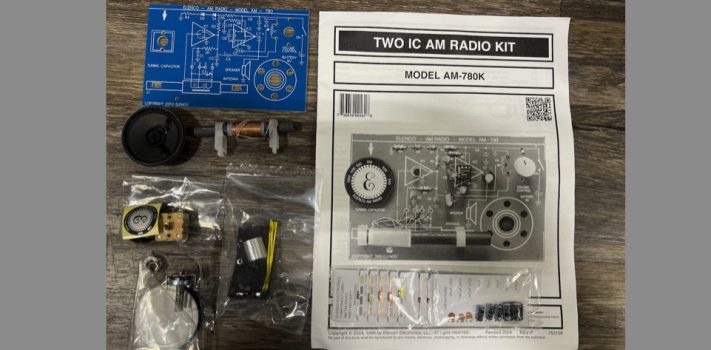
Page 6 installation steps the tuning capacitor is installed, at first, I thought I had lost the mounting screws, but with further inspection I found that they had attached themselves to the magnet in the speaker assembly so look for them there should you wonder where they are. The dial indicator is a tight fit to the tuning capacitor so hold the backside of the tuning capacitor while firmly positioning the dial onto the shaft then push it down firmly until it seats; once seated install the screw into the shaft and install the dial plate per the instructions on page 6 (figure H in the manual,)
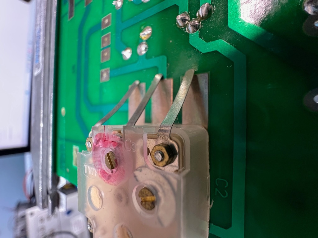
Be careful not to put side pressure on the capacitor to avoid breaking it or damaging the printed circuit board (PCB). Once you have the hardware installed for the tuning capacitor turn the board over and bend the tabs down towards the PCB and solder them in. In Figure 3 (at right) you can see how the tabs look as you have them bent towards the PCB, push them down one at a time and solder the lead flat to the PCB. It helps to pre-solder the PCB location before you push the tab(s) down then when you do push them down and solder them to the PCB all you need do is to just hold pressure on the tab and re-heat the solder you applied to the board.
Once you have everything installed on pages 6 & 7, move onto page 8 and just under Figure K there is an instruction to turn the power off. I’m not certain why this is since there were no instructions I could find to turn the power on and at this point the battery has not been installed. My best guess is that the on/off switch may be shipped in the on position. The very next line in that step was to install a fresh battery and turn the power on. This, of course, after several sets of eyes have inspected all the installation instructions, correct? And you did install the two ICs correctly. Ask me how I know this.
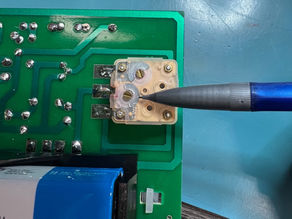
The instructions have you set the dial near the 1KHz (1,000 Hz) setting; my nearest station to that frequency is 970 AM so that would be a good setting for this step that will tune in the antenna placement. If you have a frequency generator that can generate a 1 Khz RF signal, I’d use that but try to find something close to that frequency for the placement of the antennas final location. It would be possible to set the dial indicator to 1KHz and just listen for the loudest static noise you can hear as you move the antenna itself. What is happening at this point is the alignment of the tuning dial indicator to a known point in the frequency band and the sensitivity of the antenna to that frequency as well as setting up the radio for the next steps of tuning. Figure 4 at left shows the proper location of the point where the tuning capacitor will be calibrated. My pencil is pointing to the correct tune plate, if you look down into the body of the capacitor, you’ll see the silver-looking plates that need to be adjusted. My plates are set in that photo close to the frequency range as discussed in the manual. You’s may be close, but not exactly the same as all capacitors and circuits have variations in their tuning.
Read through the tuning steps first, maybe several times before you actually try the process. Just having an idea of the process and the goal will be a great help in getting this little gem to work right. It also builds confidence where you may not have thought you could do this sort of project.
This is one very sensitive radio, so you need to be patient. I did the initial tuning of my radio on my workbench and believe me when I say that this is a very noisy RF environment. It surprised me how well this radio tuned in 970 AM — a local station. I was in a steel building with a lot of computers, pumps, test equipment and such so getting a signal inside this environment is a miracle. If I set outside this building in my pickup truck and tune in that station it is almost completely drowned out by the electrical power feeding into the building; so being able to get it loud & clear inside was a bug surprise to me.
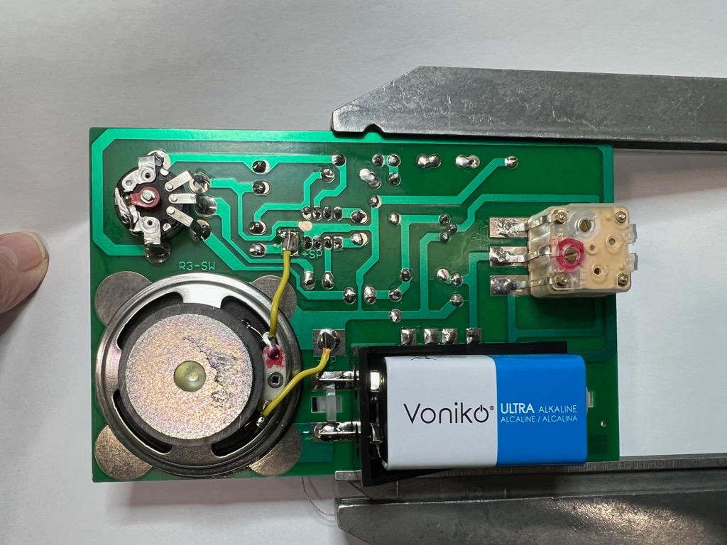
A look at the schematics tells me that it would be easy to replace the speaker (Figure 5) with a set of modern earphones. Maybe a modification to add an earphone jack that would cut out the speaker when the phones are plugged in. Just know that the audio amplifier IC2 has a lot of gain so you’ll want to turn the volume down low for silent operation should the need arise.
Pages 8 and 9 Troubleshooting
These two pages list steps to troubleshoot if you have problems after you finish building the radio. This radio is wildly sensitive and doesn’t have much in the way of AGC (Automatic Gain Control) function that one could adjust, since it is built into IC1(484 chip) and will be overpowered on a station that is very powerful and close to another station nearby of less power. It would require a different style of chip to rectify this, so just be aware of this issue. Up here where I live in Alaska, there are three nearby commercial AM stations and they are far enough apart that this wasn’t an issue for my tests on this receiver.
Page 9 has a nice list of steps you can use to make troubleshooting useful with the radio set to minimum volume and a fresh 9 V battery. These are measurements you can also make if you wish to learn to use your digital multimeter (DMM) even if you have no issues after building your kit.
My radio worked great, but I went ahead and made the measurements listed for IC-1 and IC-2 and all my readings were listed within tolerance for the circuits. There is a note above that list which says C2 should be shorted. My recommendations are to ignore that note since it doesn’t apply to the measurements for the ICs listed and only applies to the measurement listed above. Initially. I found it confusing and concerning since shorting that cap with power on could damage the ICs.
I think that in an environment where you may have several large commercial AM stations available you have more of a problem with tuning the capacitor and the antenna than not having anything at all. The sensitivity of the front end (IC1) is quite high, and the lack of external circuity to give you a better way to calibrate the AGC is going to make for one very interesting radio for the beginner.
Issues I encountered While building my radio
So, even experienced builders can run into issues, and I am no exception.
The instructions for building can be a bit difficult at first to understand; just be careful, read them slowly and make sure you truly understand what they are asking you to do, and that when you are installing a component be certain to verify the right part is in the right location in the right orientation if called for.
You should also consider that in TEOTWAWKI there may be far fewer AM stations on the air, and so selectivity sensitive issues won’t necessarily be a problem. AM radio at night (after sunset) can be a very good time to hunt for weak signals. When I lived in Michigan as a young lad, I had an old AM radio my grandfather gave me for Christmas, and I’d hunt around to hear what I could hear and was always amazed to hear a station as far away as Chicago, New York, and even communist Cuba!
Those old Megawatt stations could really get the signal out. Little did I know that I was becoming a shortwave listening (SWL) addict. Here I am an old-timer and still hunting for far-away stations with the only difference now is that I can talk back at some of them. Ham radio is a very useful hobby, it can build some very good skills for the season of angst, it could lead to a very rewarding career and will definitely help you spend all that extra money you couldn’t afford to spend. I do hope that this article has motivated you into exploring this useful TEOTWAWKI skill and barter option, may God richly bless and keep you safe.
Recommended kit completion tool links: