


Parts Required
First, here is a picture of the necessary parts. All metal parts are made of brass, and all plastic parts are made of PVC.
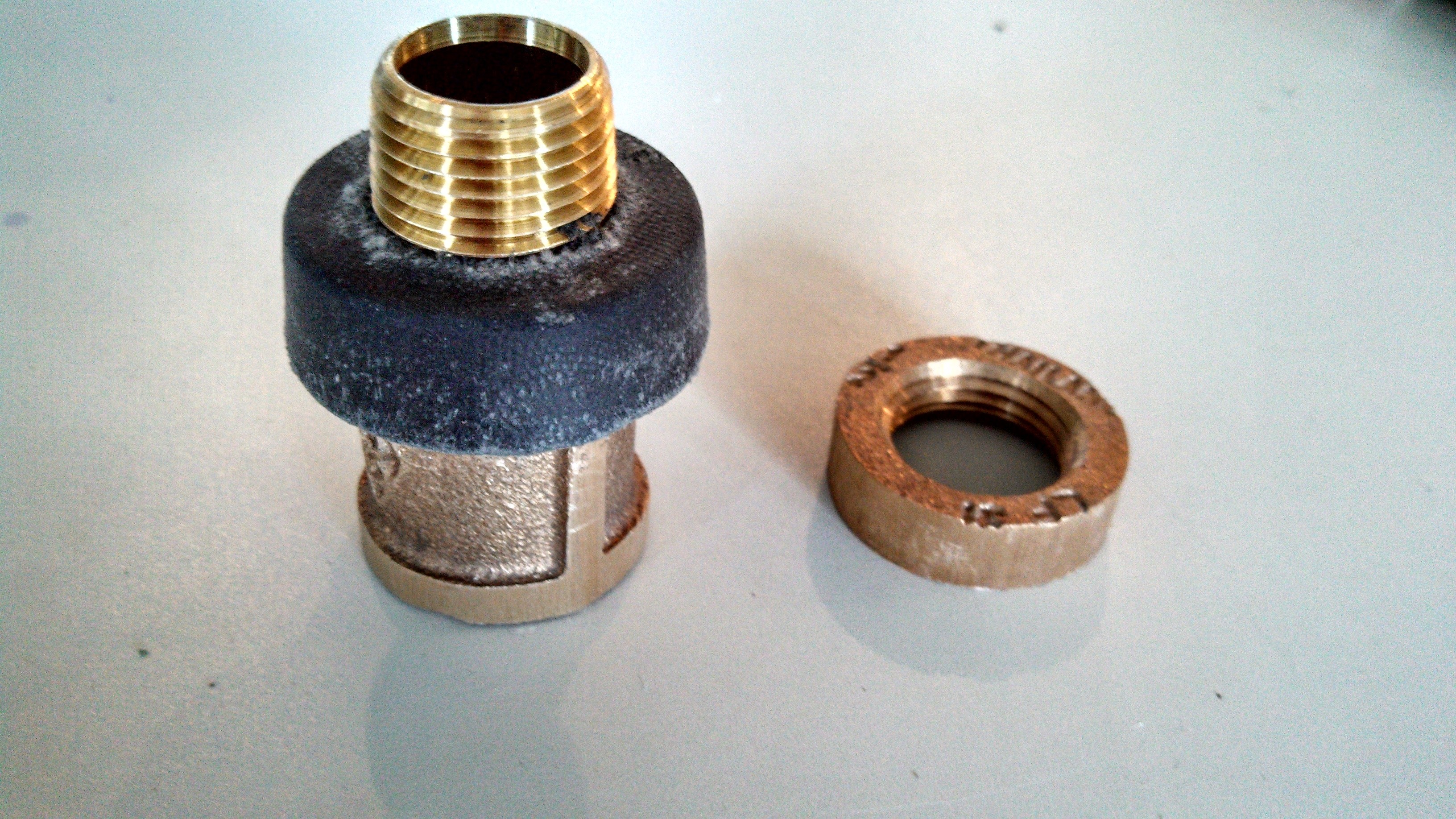
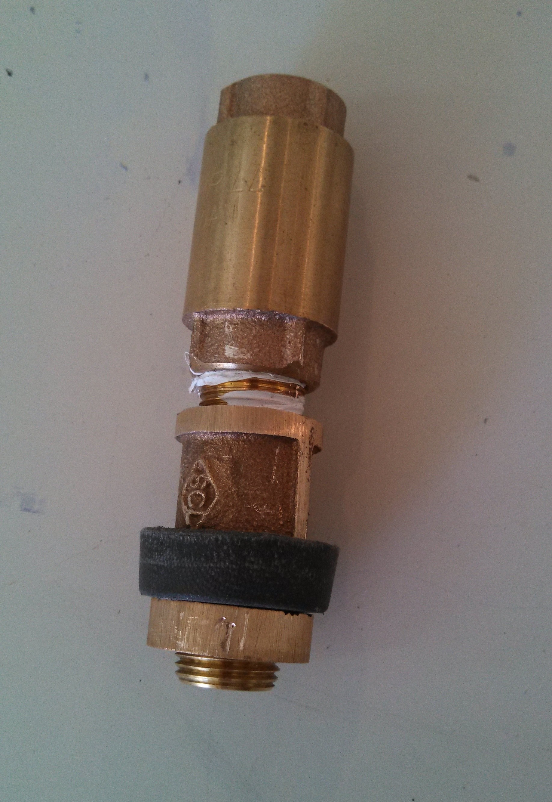
Brass parts and seal:

- 1 @ 1/2” x 3” brass nib
- 2 @ 1/2” x 1” brass nibs
- 2 @ 1/2” threaded brass coupler
- 1 @ 1/2” threaded brass ring/nut (I had to sand mine down as it was hexagonal)
- 1 @ piston cup seal – McMaster Carr part # 9411K12
- 1 @ 1/2” brass check valve (I used Merril 800 series CV50)
- 1 @ 1 1/2” brass check valve with filter screen
PVC Parts:
- 1 @ 1 1/2” male adapter t x s
- 1 @ 1 1/2” coupler t x s
- 1 @ 1/2” x 3/4” male adapter t x s
- 1 @ 1 1/2” poly pipe male adapter t x s (dark gray in picture
- 1 @ 2 feet of 3/4” schedule 40 PVC pipe
- 1 @ 2 feet of 1 1/2” schedule 40 PVC pipe
Additional Items:
Assembly
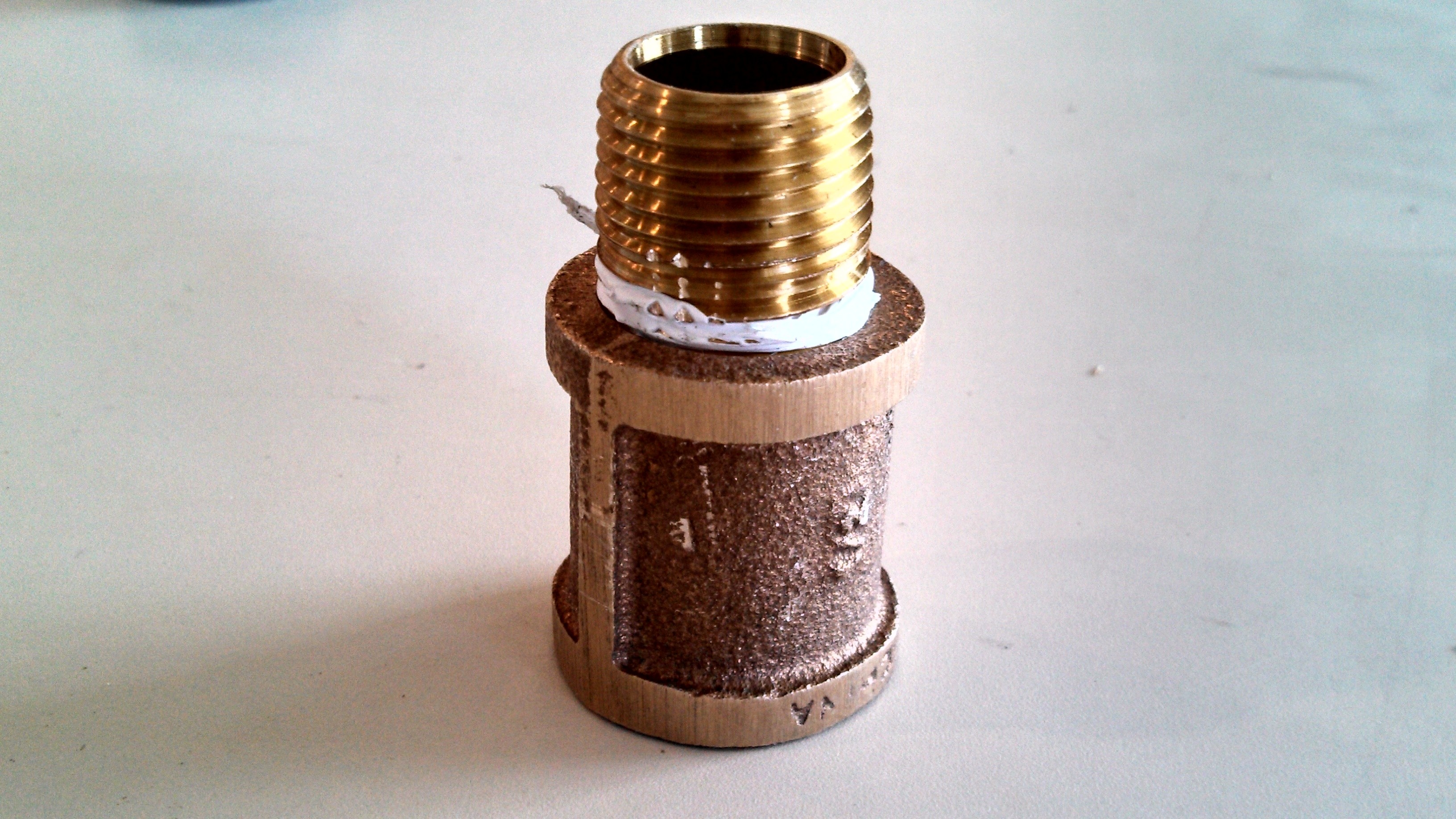
Step one – plug one of the brass couplers with JB weld:
- Place thin plastic over end of brass nib and screw in threaded coupler as deep as it will go using pliers.
- Or cut a small disk of card stock to fit in the space between the threads coming from each end. Make sure and prep the coupler with acetone, brake cleaner, etc. to remove any oils used during machining.
- Carefully pour JB weld into coupler until it just reaches the threads coming down from the top.
- Let JB weld cure.

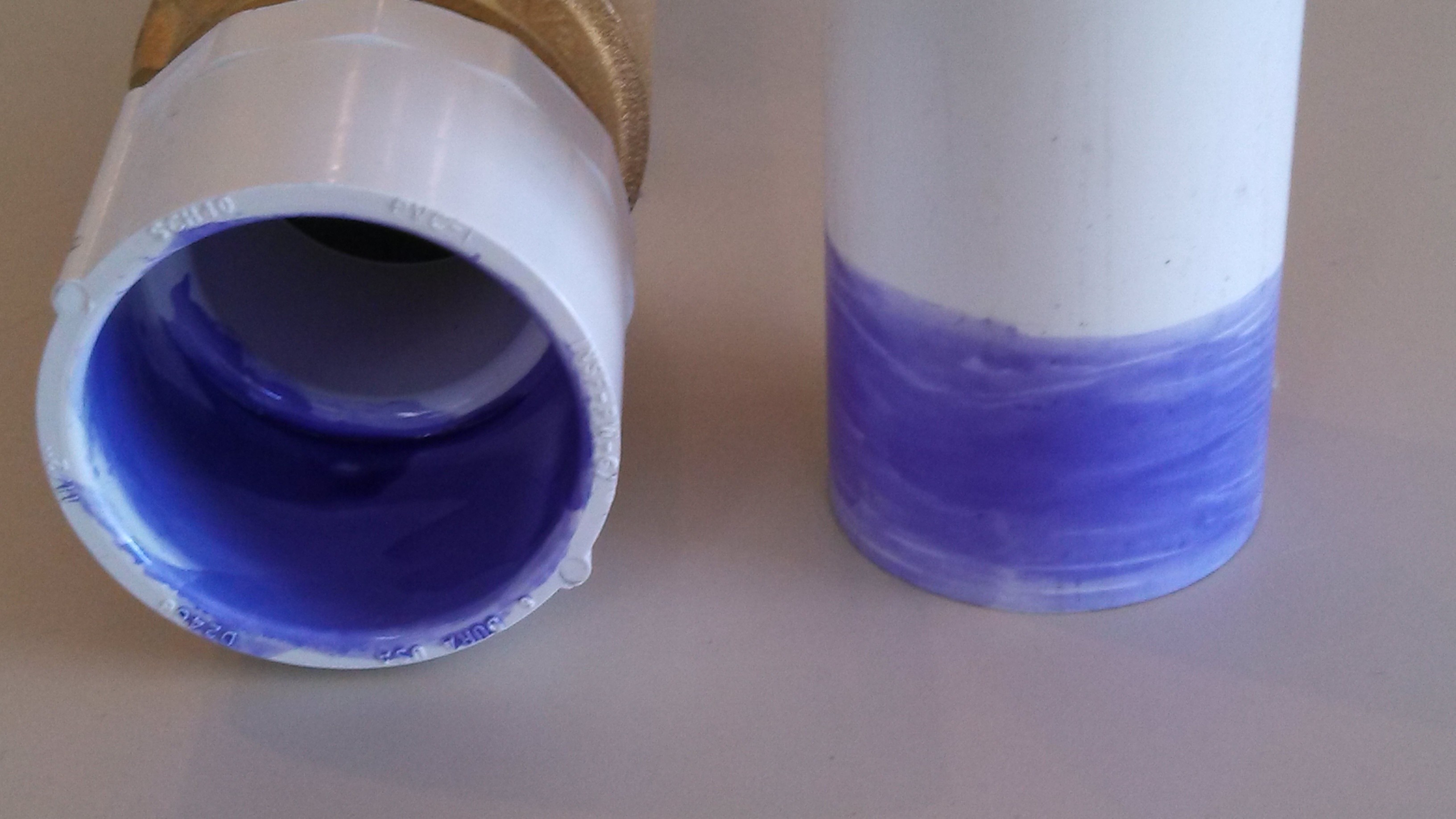
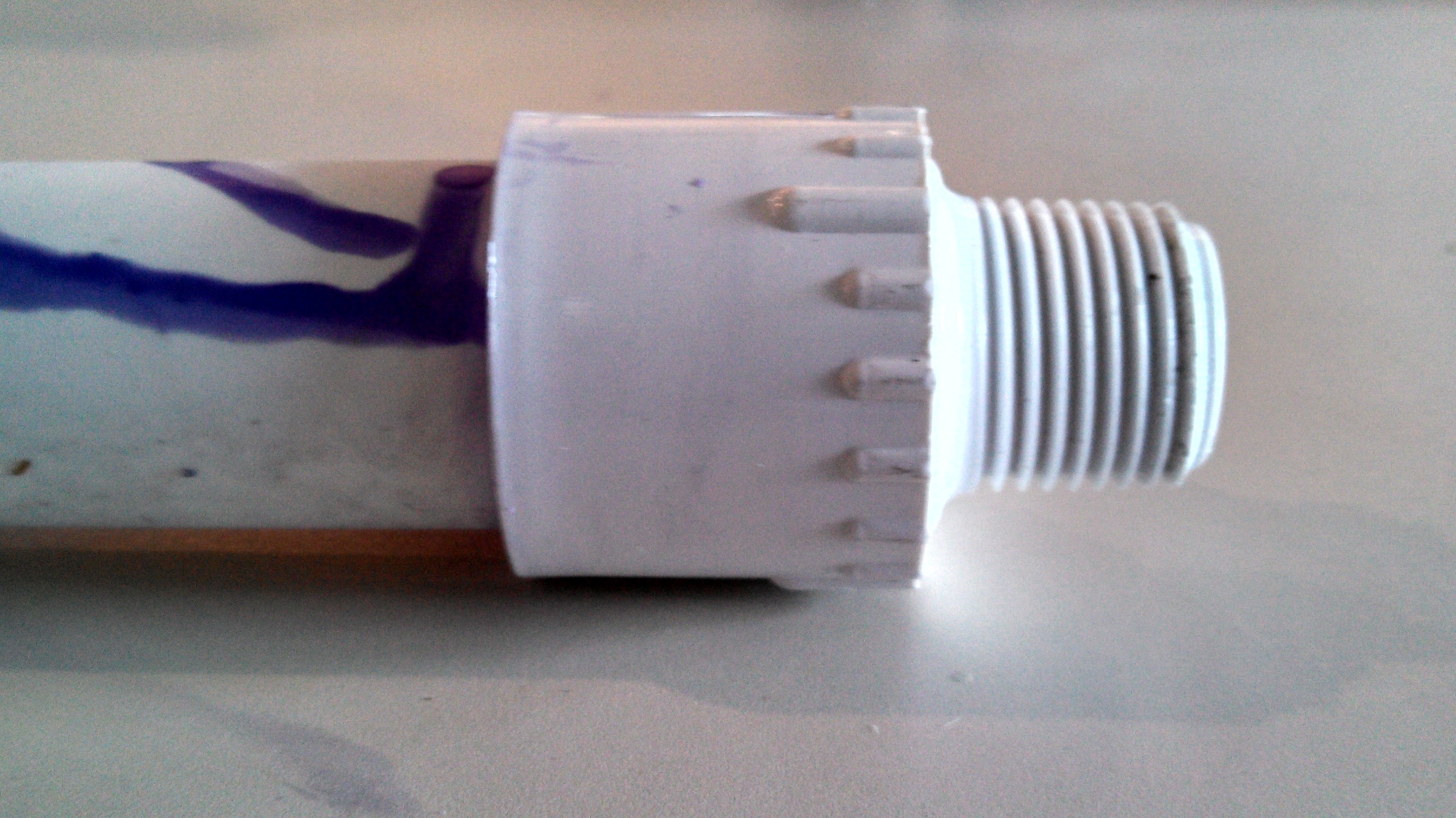
Step two – assemble PVC pipe and fittings:
- Prime 1 1/2” male adapter and one end of the 1 1/2” PVC pipe with PVC primer.
- Apply clear glue to primed surfaces and insert pipe into the slip end of the male adapter. Hold together for 30 seconds (it wants to push itself back out if you don’t hold it).
- Screw this pipe into the female end of the screened 1 1/2” check valve.
- Repeat primer / glue sequence for the other end of the 1 1/2” pipe and the slip end of the s x t 1 1/2” coupler.
- Repeat primer / glue sequence for the end of the 3/4” pipe and the slip end of the s x t 3/4” x 1/2” male adapter.
- Lay both assemblies aside.
Step three – assemble inner check valve assembly:
- Apply Teflon tape to one end of a 1/2” x 1” brass nib and screw firmly into 1/2” brass coupler using pliers.
- Ream out piston cup seal center to allow it to screw over top of nib.
- Screw piston cup seal down over nib with cup side against coupler.
- Tightly screw brass nut over nib.
- Apply Teflon tape over one end of the other 1/2” x 1” brass nib and screw tightly into threaded brass coupler.
- Apply Teflon tape over other end of 1/2” x 1” brass nib just inserted into coupler.
- Screw brass nib into 1/2” brass check valve. Make sure check valve direction allows fluids to flow away from the end where the piston cup seal is located.
- Drill a 3/8” hole all the way through the side of 1/2” x 3” brass nib, rotate 90 degrees and drill all the way through again but about 1 inch away from the previous holes.
- Apply Teflon tape to both sides of the 1/2” x 3” brass nib and screw one end into the brass check valve and screw the other end into the plugged brass coupler.
- Screw male end of the 3/4” x 1/2” male adapter into the plugged brass coupler.
- Set this assembly aside.
Step four – put pump together:
- Liberally apply silicone grease to outside of piston cup seal and to inside of 1 1/2” PVC pipe.
- Insert inner pump assembly into the 1 1/2” PVC pipe assembly.
- Screw the 1 1/2” poly pipe adapter into the threaded end of the 1 1/2” PVC coupler.
Step five – place into well and secure:
- Attach the 1” x 160 psi NSF polyethylene pipe to the end of the 3/4” pipe to reach the bottom of the well plus about 2 feet.
- Attach enough 1 1/2” poly pipe to the 1 1/2” poly pipe adapter to reach the bottom of the well.
- Secure the larger poly pipe to the top of the well.
- Insert a 1 1/2” poly pipe to PVC adapter onto the larger poly pipe.
- Attach a threaded female coupler to the adapter.
- Glue a tee to this coupler with the side opening of the tee perpendicular to the poly pipe.
- If you want, glue a 1 1/2” x 1” reducer bushing to the top of the tee where the smaller pipe comes out; the inside of the reducer should be reamed out to allow the smaller pipe to slide easily.
- The smaller pipe should stick out of the top opening of the tee.
- Water will come out the side opening of the tee.
That’s it. You are done!
Using the Manual Water Pump
To use:
- Fill the outer pipe with water, or begin pumping to self-prime the outer pipe; expect to lift the weight of the entire smaller pipe while the outer pipe fills.
- Once primed, move the smaller pipe up and down to begin pumping; water should come out of the side of the tee both with the up stroke and with the down stroke.
- The force required to pump the water out should not change as the water travels up inside of the poly pipe or with the depth of the water source.
I have not patented this idea nor will I. I haven’t looked to see if someone else has patented this idea either. I only hope the ideas presented in this paper are useful. Please pass them on.