When connecting devices to your security system, there are two basic methods used: wired and wireless. In a later article, I will cover the advantages and disadvantages of both systems and when they are appropriate to use. However, the idea for this first installment was created as I had to repair some Ethernet cabling at a customer’s residence. The customer was familiar with Ethernet connectors and had cobbled together a connector when he moved his computer system to another area of the residence. He had lost a wifi radio to a lightning storm when he shouldn’t have, and we discovered the root of the problem was the connector he installed on the cabling.
EMP is a huge concern anytime you are dealing with electronic hardware, and there are some steps that you can take to minimize the risk of your equipment. Everyone knows about installing a quality surge protector for equipment that must be live, storing unused equipment in a Faraday cage, and implementing other such preps, but few seem to realize that the data cable connecting their computer or security system is just as critical. Long wires attached to your computer represent the greatest danger, as they act as antennae to pick up the magnetic energy from an EMP pulse, whether generated by a nuclear, solar, or lightning event, and they turn it into electrical pulses that damage sensitive electronics.
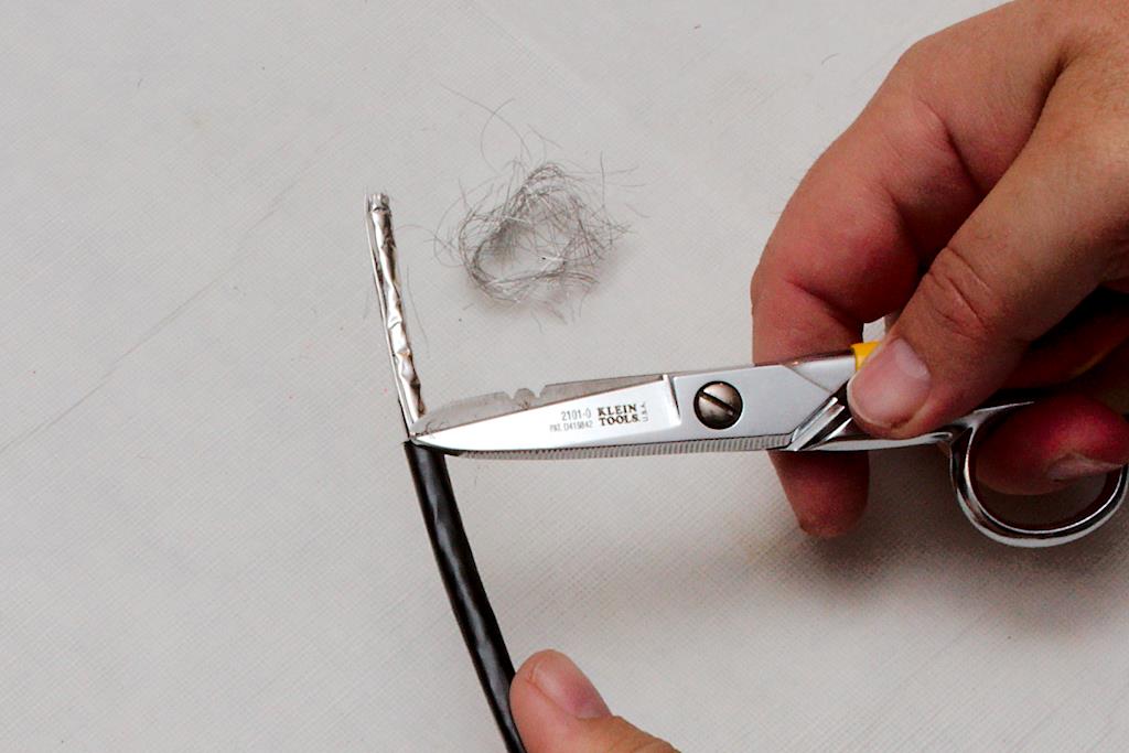
One of the easiest and best methods of protection is to simply provide a better, alternative path to ground for the electrical impulse. Shielded cabling and grounded connectors achieve just such a result. There are many types of shielded Ethernet cabling; the two that we currently use– Ubiquity’s Tough Cable Pro and Tough Cable Carrier– are among the best. We also use Ubiquity’s Tough Cable RJ45 connectors, though you can use any grounded RJ-45 connector. The tools required for these connectors are simple but specialized. Figure 1 Figure 1is a picture of the tools we currently use. The only one required is the RJ-45 crimper tool on the left. This particular model is an Ideal 30-696 and has a ratcheting feature so you can regrip in the middle of a crimp without ruining the crimp. It’s nice but not necessary. Any RJ-45 crimper will work. You will notice the blue cushioned grips are missing on mine. While the cushions are nice, they tend to slip off as you work the pliers. I eventually got irritated enough that I just pulled them off and threw them away. Despite installing thousands of connectors, I’ve never missed them. You can do without the remaining tools, but they will make your work easier. The yellow plastic tool merely cuts the sheath on the Ethernet cable without nicking the conducting wires. Any model will work, but I prefer one with a ring, as it makes it easy to insert your finger and rotate it around the cable. A pair of sharp snips comes in handy, and I like the Klein 2101-0 snips. The yellow handle fits in your palm, gripped with your ring and pinky fingers. Your middle finger slips through the silver ring, and you can open and close them at will, without the age old issue of getting your finger stuck in a ring. This is a nice feature when you are picking them up and using them often during the course of your work. Those of you who’ve had to stop your train of thought to shake the snips off of your finger know what I mean. The multi-tool (with needle nose pliers) is probably the next most useful tool. From crimping the grounding wire to opening up the can of tuna you brought for lunch, it’s hard to imagine life without it. I prefer this Gerber model, but any model will work. The last tool is a general purpose crimper designed to fit yellow insulated lugs. This tool serves a special purpose that will make your life much easier.
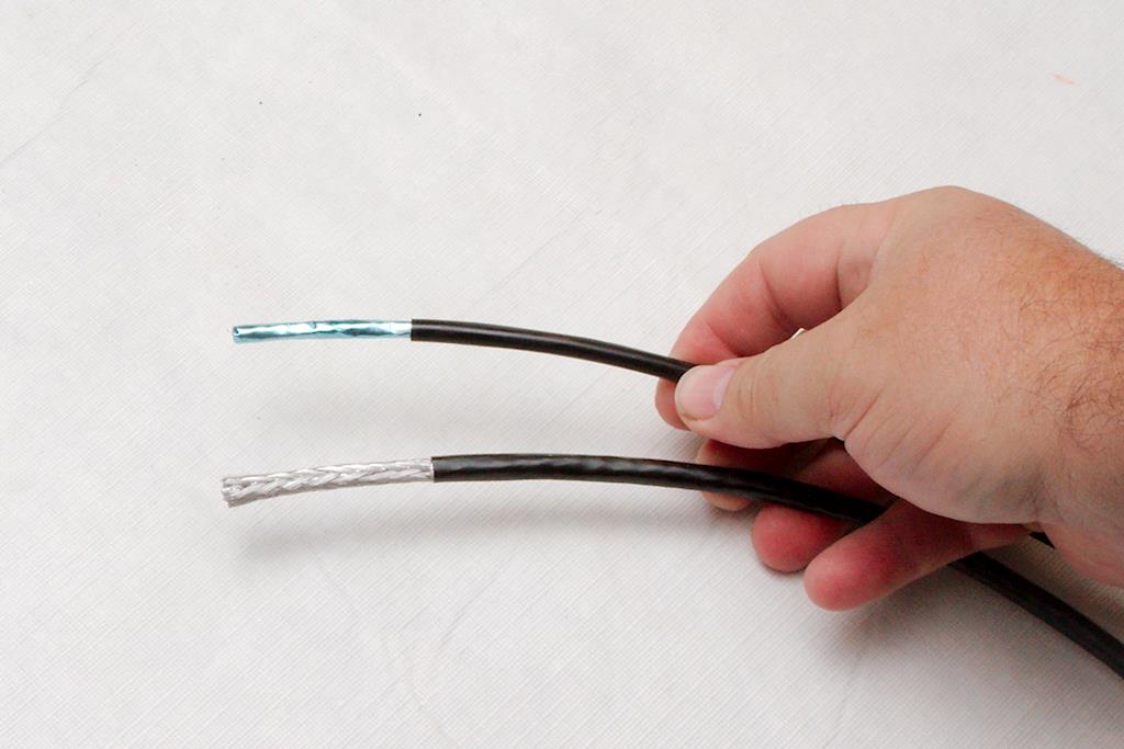
Both cables that we use are rated “5e”, but the carrier cable is much tougher. Figure 2The braid provides an incredibly tough cover, and while it certainly works as a shield, I consider the physical protection more important. If we are installing cabling outside or near items that could potentially cut the Ethernet cable, we choose the carrier rated cable. For others, like interior runs, attic installs, or more protected areas, we will use the pro cable. Both cables are UV rated, and even after five years none of the cables exposed to direct sunlight are having any issues. You can get silicon gel-filled cable as well for waterproofing (or direct burial), but the hassle of dealing with the nasty goo just isn’t worth it for us. These cables provide adequate protection, and even in the rare instance where the jacket was damage and allowed water into the cable, there were no ill effects on the data handling of the cable. The few instances where we knew water was in the jacket, we simply sliced the jacket at a low point in the cable to allow the water to drain out. It’s probably not the best policy, but don’t fix what isn’t broken. Besides, this cable is expensive at over $0.20/foot.
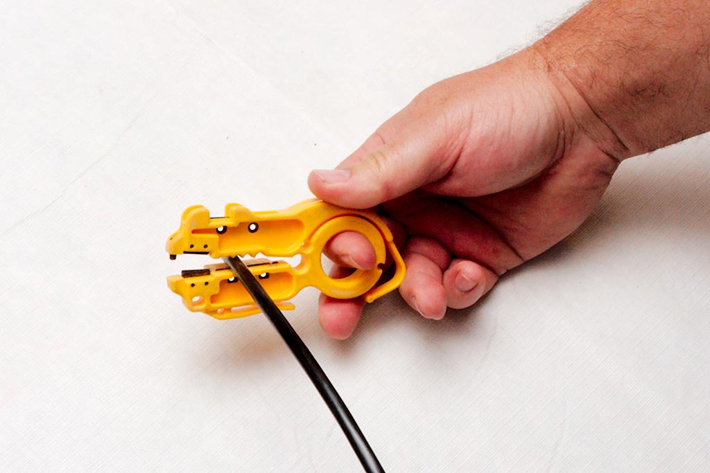
To start, you have to strip the jacket off of the cable. The amount that you strip will be based on your comfort level. Figure 3 As you get comfortable with the procedure, you will strip back less and less. Remember, any thing more than what you need is simply trimmed off and is a waste. We tend to strip back about two inches, which gives a decent tail to work with the wires. Place the Easy-Strip on the wire, let its own spring tension apply the cutting force, and spin it around the cable once or twice. When stripping the Pro cable, you have to be careful not to cut into the foil underneath. Your goal is to just score the jacket so that you can slightly bend the jacket and cause it to split on the score. When properly cut, you can separate the jacket without the foil being damaged like in figure 4. If you cut the foil, you will probably have to try again. Figure 4
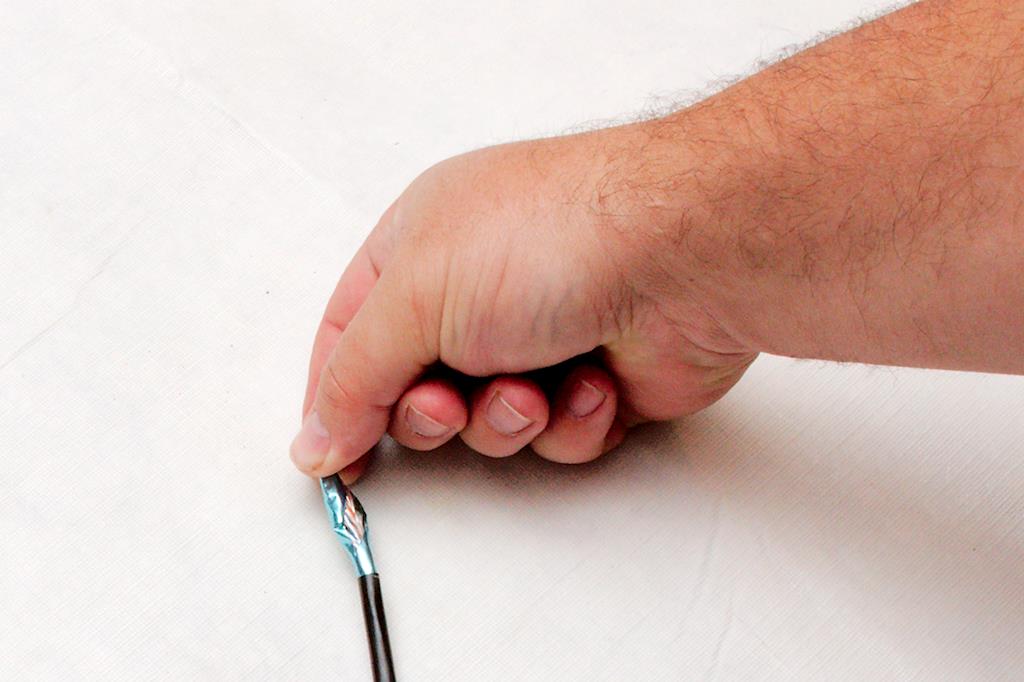
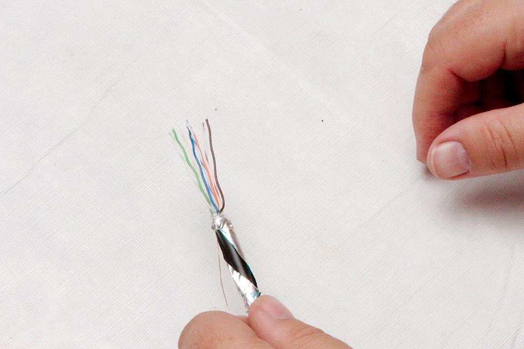
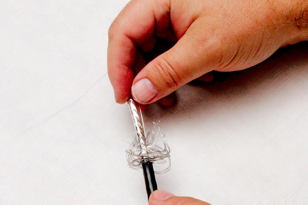
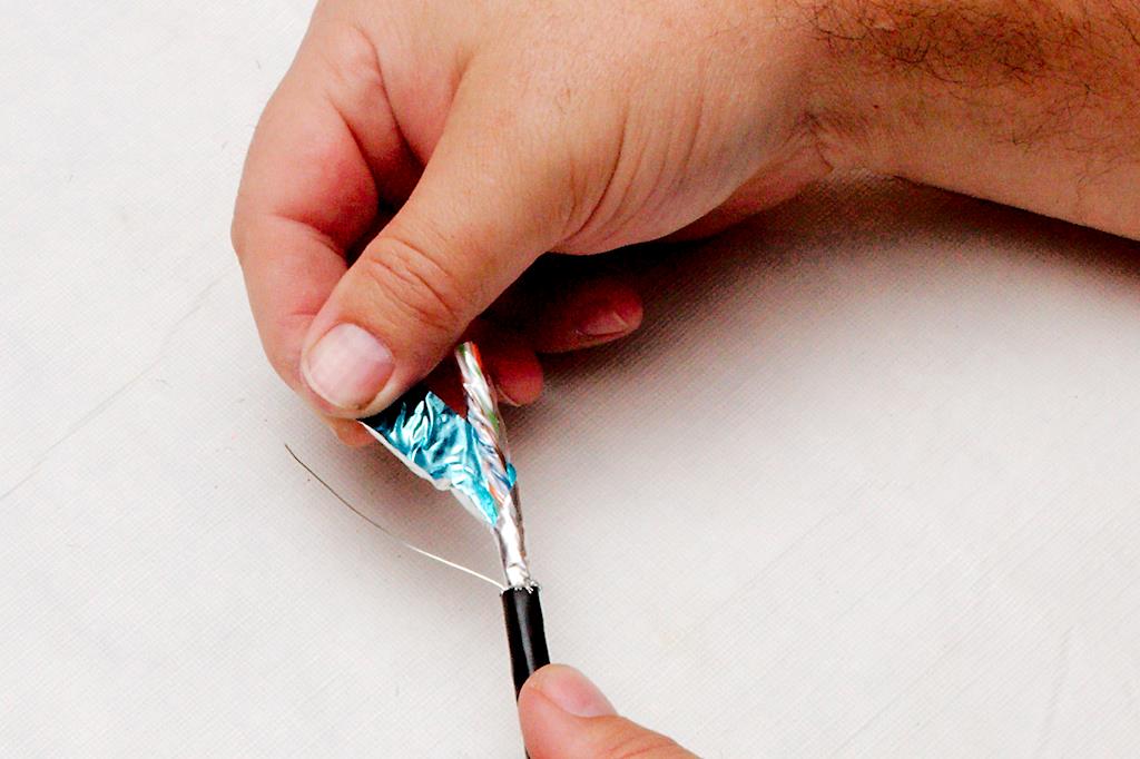
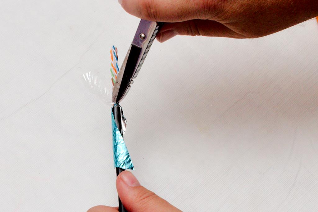
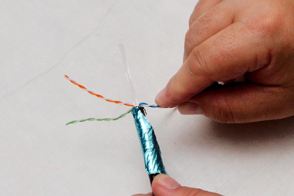
If using the “Pro” cable, you must carefully unwrap the foil ground. This foil is wrapped in a spiral around the cable, and one side will be easy to unwrap, but the other will not be easy, as the foil is tucked under itself. Figure 5 Gently twist the cable to loosen the foil wrap and work it loose. You do not want to tear the foil at this stage. Once you have unwrapped the foil, gently pull it back over the jacket of the cable Figure 6. You need to fold it back right where the jacket stops, and it is important not to tear it here. You can use your fingernail to work the fold right up against the jacket edge. After this, you will have exposed the ground wire and the conductors wrapped in a plastic casing. Carefully untwist the plastic casing, and cut it as close as you can to the foil. Figure 7 It is sufficient to nick the casing with snips and then tear the plastic casing off. Use the snips to clean it up, if it does not tear evenly.
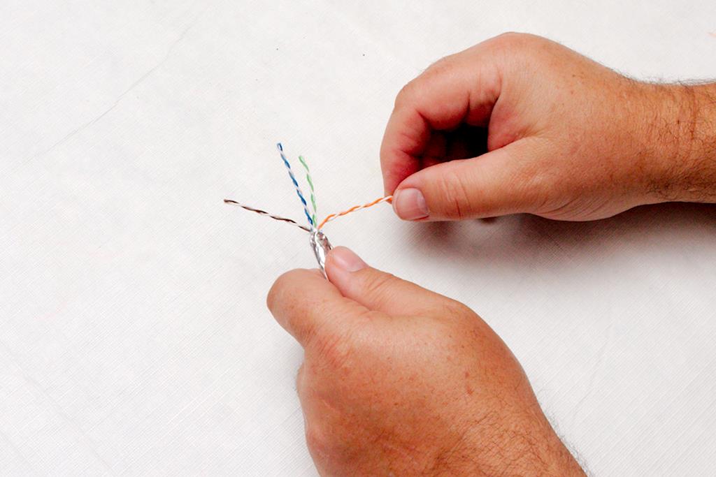
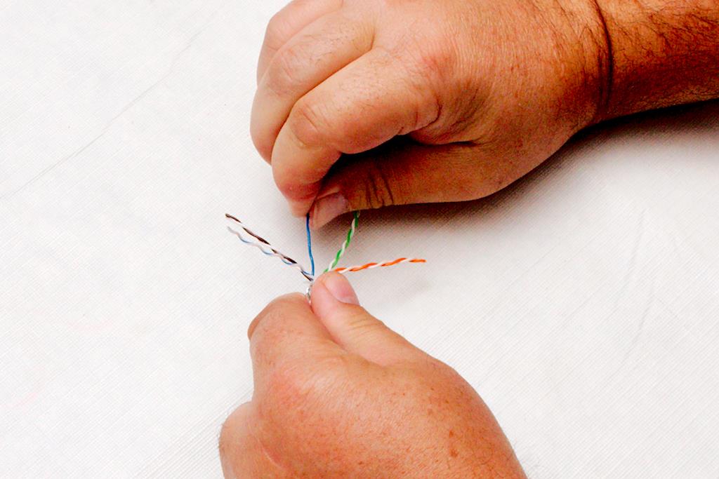
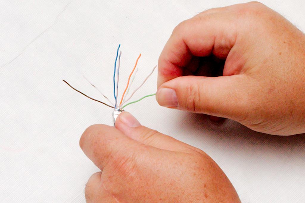
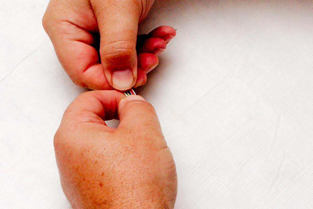
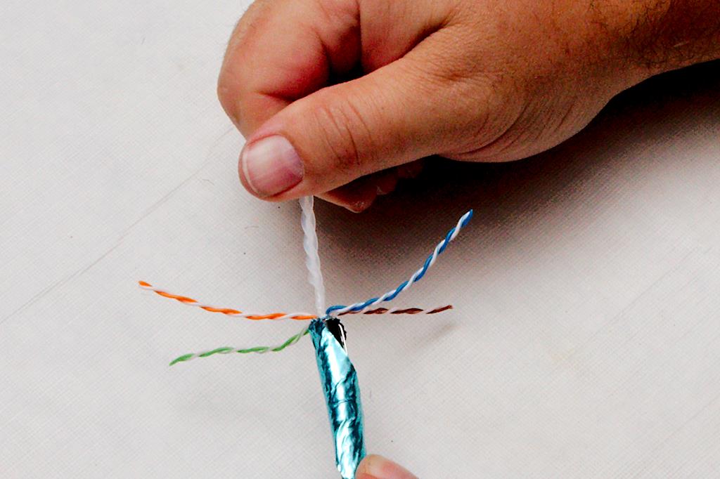
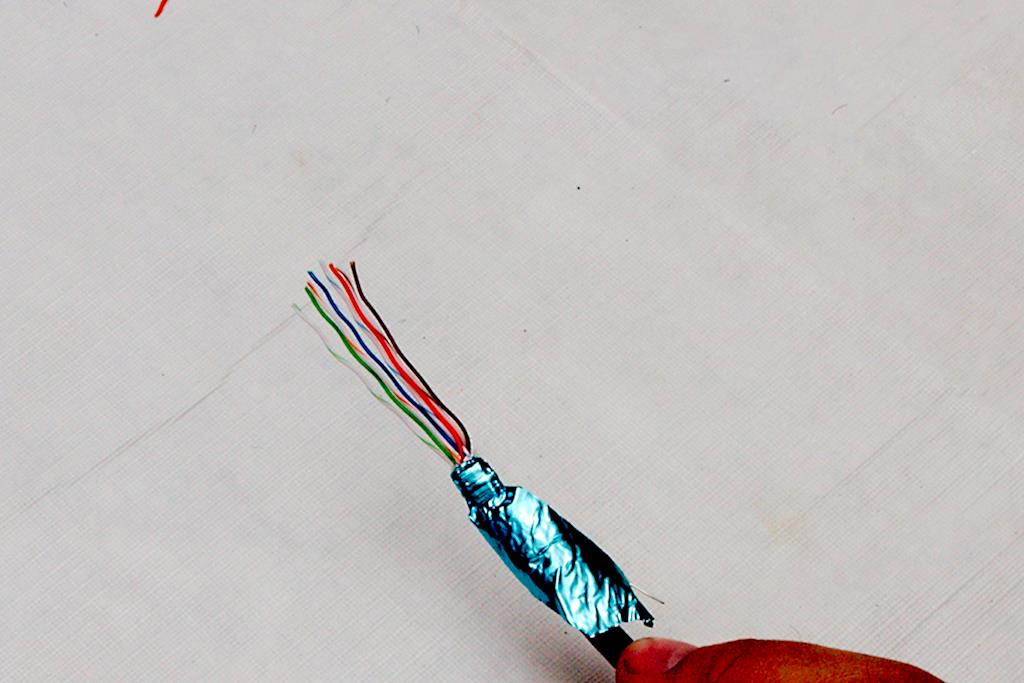
Figure 8 You then want to separate the twisted pairs of wires from each other. Here you will be able to see a major difference between cat 5 cable and cat 5e. On 5e cable, each twisted pair will have a different twist to it. Some will be tighter, and some will be looser. This helps with signal leakage between the pairs and allows for a higher speed of signaling. Once the pairs are separated, untwist them to where the foil is. Figure 9 As you untwist the individual wires, pinch the cable between the fingers of your other hand and pull each individual strand through your fingers to take as much of the kink out as possible. The straighter the wire the easier the whole process will be. You probably want to keep the colors close together, though once separated it may be difficult to tell the white wires with the color strip from each other in poor light conditions. This is one area where a headlamp is an advantage, even in regular room light. Figure 10 When finished, all the wires should be pointing in different directions with no severe kinking in them as in figure 10.
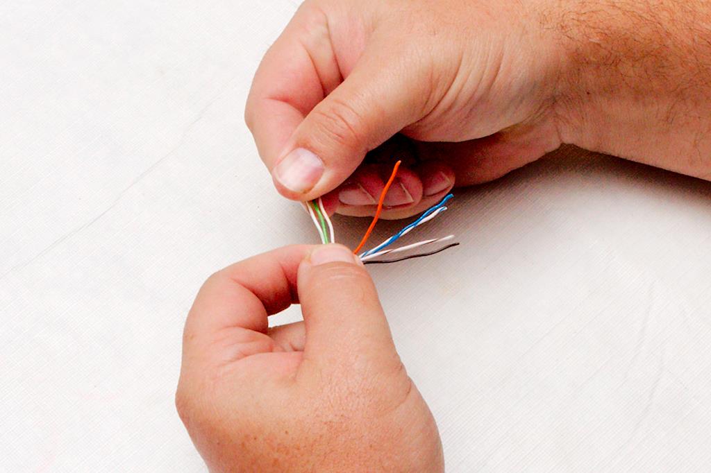
Now, while pinching the wires (at the point where the wires exit the jacket) between the forefinger and thumb of your left hand (for us “righties”), begin to line the colors up. Figure 11 There are two standards, and it doesn’t matter which standard you use as long as both ends are the same. We use the T568A standard with the resulting color lineup of white-green, green-white, white-orange, blue-white, white-blue, orange-white, white-brown, brown-white. Be mindful of how the wires come out of the jacket and don’t be afraid to rotate the Ethernet cable or disentangle the wires. Your goal is to have the wires exit the jacket and be separated into their specific channels as soon as possible. Figure 12 Don’t be afraid to bend the wires to put a “set” in them so that they will hold their positions when you turn loose of them. If they spring out of place when you turn loose, you will really struggle while placing the connector on.
Figure 13 Once the wires are positioned, pinch them in the correct order between the forefinger and thumb of both hands and slightly bend them. Figure 14 Then bend them back the other way allowing the wires to slide between your fingers. Work them back and forth as you slide your fingers from the jacket end to the wire end. What you are doing here is working the remaining kinks out and forcing them to lay parallel to each other in the correct order. Figure 15
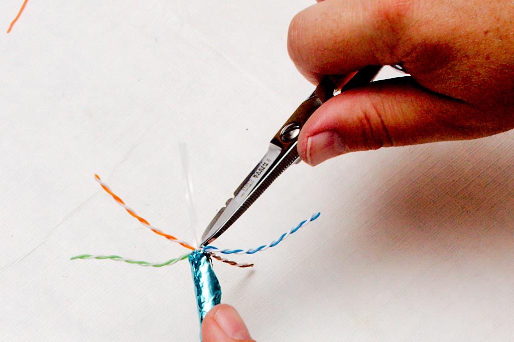
Finally, use the cutting edge of the crimpers to cut the wires to the correct length Figure 16. This may take some practice to get right, but you want enough length that the wires will go all the way to the end of the connector but not so much that you can’t fit the cable jacket in the connector also. The right amount will be somewhere between 3/8” and 5/8”. Cut it long, as you can always take a second cut to shorten it. If you cut it short, you will be starting over from the beginning. Figure 17 To get a good idea, hold the connector next to the cable with the cable sheath as far in the connector as you want it to go. Then cut the wires so that they would be at the end of the connector. Figure 18
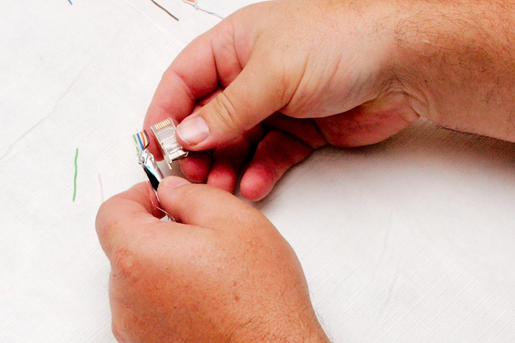
Figure 19 Then insert the connector onto the end of the cable with the latch portion of the connector pointed down. This will be a tight fit, and you need to make sure that each wire slips into its proper channel in the connector. This is where those spring-loaded wires will tempt you into cussing like a sailor if you didn’t work the kinks out beforehand. Cock the connector from side to side while applying pressure against the cable to work it into the proper position.
Figure 20 Figure 19 shows where you should end up. If you look at the end of the connector, you should clearly see each wire pushed up against the end of the connector. if the wires are set slightly back, it may still be okay, as the electrical connection is made about 1/8” back into the connector. Occasionally, the wire will slip back into the jacket with the pressure you apply if you do not pinch the jacket hard enough. If you can’t get the wires all the way in, don’t be afraid to pull the connector off and adjust the wires, but this is the make or break time. If all goes wrong, it’s back to the first step you go.
Before you crimp, take another look at the wires in the connector; use a magnifier if you need one. Make sure each wire is positioned in the proper channel. Finally, insert the connector into the crimper, and crimp it all the way down while making sure your wires don’t pull out in the process. Figure 21. The best way to ensure this is to use a ratcheting crimper, and apply pressure into the connector with the cable as you crimp. Crimp until the crimper is all the way through the ratchet cycle.
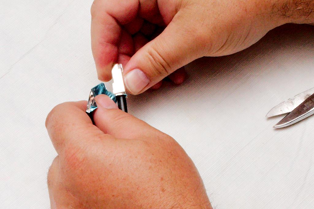
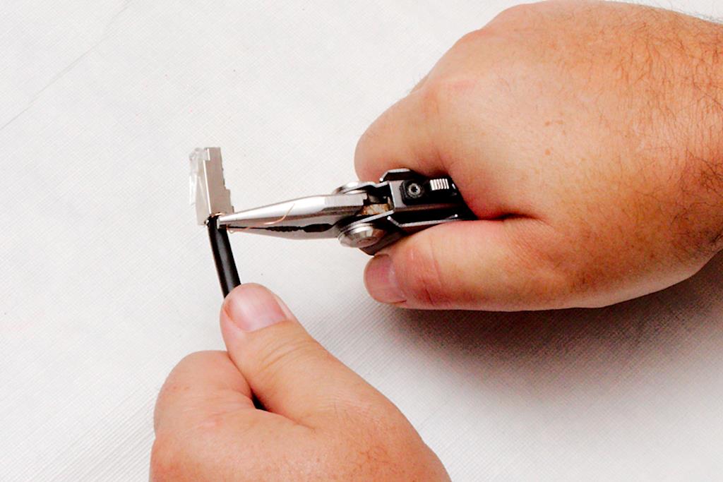
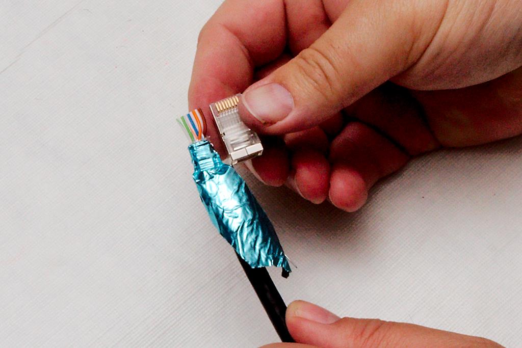
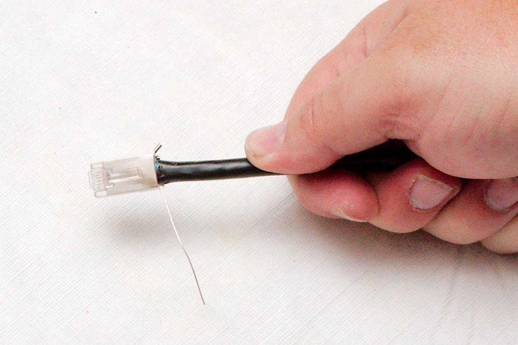
Next, use your snips to nick the foil right up against the connector Figure 22; and tear the foil off Figure 23, making sure not to pull the connector off or damage the ground lug on the connector or the grounding wire. The closer you tear the foil off to the connector, the cleaner it will look. You can also take your fingernail and push any jagged edge of foil that you can’t tear back up into the bottom of the connector. Then either using your needle nose pliers or your fingers, thread the ground wire through the connector into the ground lug. Figure 24 Make sure to thread it from the front to the rear. Once you have it threaded all the way through, use your needle nose pliers to crimp the lug onto the wire. If you are not plugging this into a socket that is grounded, you can crimp a loop onto the end of this wire and ground it to a nearby ground with a screw. Otherwise, clip it off next to the ground lug as in figure 25Figure 25; and push the ground lug back toward the cable jacket so it doesn’t snag on anything.
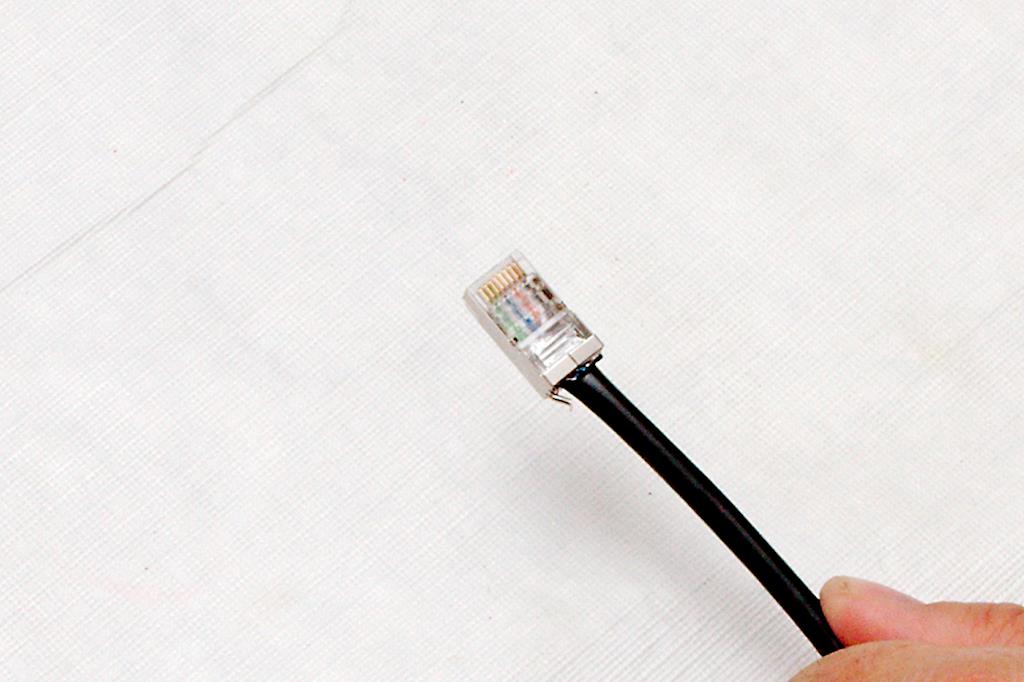
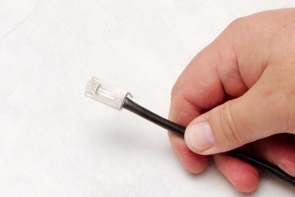
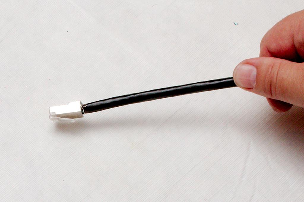
When done, inspect the connector. Figure 26 You want to make sure that 1) all the colors are in the right order. 2) the jacket and foil are inserted into the connector beyond where the plastic crimps the cable, 3) the metal on the cable makes good contact with the foil, and 4) the ground wire is undamaged, crimped appropriately and correctly positioned so that it won’t snag on anything like in figure 27 Figure 27
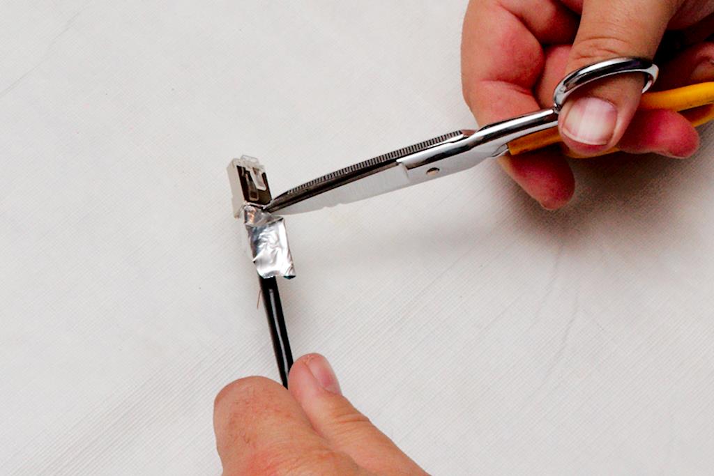
Working with the carrier cable is very similar but a bit more difficult. First of all, you have to deal with the protective braid shown in figure 28.Figure 28 After you have stripped the jacket off of the cable, you need to push the shield back onto the cable to loosen it. This cable is much easier to strip the jacket off of because you don’t have to worry about nicking the foil underneath. If you nick a few strands of braid, it’s no big deal as you will trim these off anyway. Once you’ve loosened the braid by pushing it back, it will start to unravel. Don’t worry about that, but push it hard enough that the braid will stay perpendicular to the jacket when you turn loose of it as shown in figure 29.Figure 29 Then carefully take your snips and cut the braid as close to the jacket and foil as you can, without hurting either one. Figure 30
You will notice that the ground wire is now located outside of the foil rather than inside of it. make sure you do not cut this drain wire when cutting the braid off, as it is integral to the grounding operation of the connector. Figure 31; Unwrap the foil and bend both the foil and ground wire back along the cable jacket as you did before. Depending on which end of the cable you are working on, you may have to twist the signal wires to be able to untwist the foil. Once the plastic casing is exposed, cut it off as before. figure 32
When you are bending the signal pairs back, you will notice an anti-crossover device in the center of the wire Figure 33. This makes sure that the wires to not get twisted up and greatly improve the signal handling capability. Even though this wire is rated 5e, these are features that you find on cat 6 wire and work wonders when dealing with gigabyte speeds. Figure 34 Remove this device by clipping it gently with your snips, being careful not to cut the wires as shown in figure 34. I find that clipping two wings is generally enough, and then you can twist it to break it right at the clip as in figure 35. Figure 35
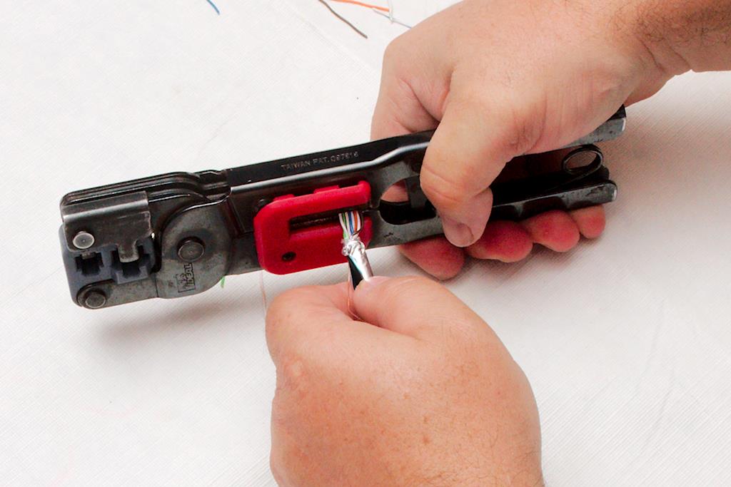
Now go through and separate the wires, and then line the colors up as you did before. Here is where you will run into trouble and where our method differs from the manufacturer’s instructions. A significant part of the structural integrity of the connector/cable interface is having the cable jacket crimped inside of the body of the connector. However, this cable is a much larger diameter than regular Ethernet, nearly approaching the size of RG-58 coax. It’s like putting the proverbial round peg into the square hole. The manufacutre will simply have you put the crimp in off the jacket, but if you do that, you will notice that it creates a weak point. If any bending tension is on the cable when you insert the connector into the socket, the bend will turn to a kink right at the back of the connector. it also puts the strain of the connection directly on the grounding foil. To over come this weakness, we used to use a pair of pliers and form the round end of the cable into a rectangle that would fit into the connector. Then one day, I happend to notice that the yellow compression crimps were just the right size. After you line the wires up, insert the cable into the crimpers as in figure 36 Figure 36 so the end of the crimper is at the end of the jacket and the wires are inline with the crimper jaws. Then run the crimper through the full ratchet cycle. it will press form the round jacket into a rectangular form that will just fit inside the RJ-45 connector. Figure 37 This cable is stiff and hard to work with so don’t be afraid to twist, bend and work the wires as you line them up just right. Follow through with the trimming of the wires as you did before, using the connector as a guide for length. Figure 38 It will be more difficult to work this cable into the connector, and you will probably need more wire length than you will using the Pro cable. In figure 39, you can see that there wasn’t enough length on the wire,Figure 39 and the ends do not go all the way to the end of the connector. I will have to cut this off and restart from the beginning to make a usable end. Don’t skimp here. Marginal connections will drive you nuts on POE (Power over Ethernet) or Gigabyte installations.
Once the cable is inserted into the connector properly, crimp it as before and tear the foil off.Figure 40 Notice in figure 40 how the jacket of the cable is slightly distorted by the crimping process. The signal wires are not damaged, and the structural integrity of the connection is greatly improved by getting the cable jacket inside the connector when you crimp.
One last note. Figure 41 Take a look at figure 41. About half the time, the ground wire will be on the opposite side of the cable as the ground lug on the connector. You might think that it would be an easy matter to simply rearrange the wires so that the ground lug is always on the proper side. However, because of the stiffness of this cable and the tight tolerances that you are working with, it is always easier to arrange the wires where they are least resistant and then simply run the ground wire along the bottom edge of the connector to slip it into the ground lug of the connector. Figure 42 When done properly, the connector is still strong and neat and you won’t really notice the extra travel of the ground.
Now, go and soak those hands in warm water. If your fingers are not aching after about the third or fourth connector, you are superhuman.
#1 Trusted Gravity Water Purification System! Start Drinking Purified Water now with a Berkey water filtration system. Find systems, replacement filters, parts and more here.
#1 Trusted Gravity Water Purification System! Start Drinking Purified Water now with a Berkey water filtration system. Find systems, replacement filters, parts and more here.