


(Continued from Part 1. This concludes the article.)
C45 INSTALLED UNDER PCB (LEFT) IC1 SOCKET PINS IDENTIFIED (RIGHT)
There will be many other such steps in this process, so I’m now going to fast forward to pages 9 through 14 after completing all the installation of parts in those pages and report on the tests that are part of the process up to that point. (NOTE: the top of page 12 indicates that if you don’t have the audio generator and the oscilloscope to skip to part 1B) I chose to do the tests and report my findings for the readers knowledge and discuss why the tests are pertinent to those completing the course as an educational directed effort.
(NOTE: Pay very close attention when you install C44 and R45. I will not tell you why, but should you choose not to, you will eventually be scratching your head and maybe wondering why the magic smoke escapes …)
PAGE 10 FIGURES 6 AND 7
This page has all preliminary tests using just your DMM.
Figure 6 Idle Current Test
The purpose of the tests is to verify the idle current of the radio at this point of the course. My test showed the idle current as 0.7uA. That was well within the range specified for this test at this time.
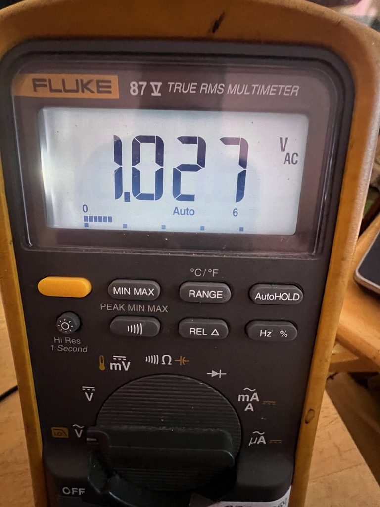
Figure 7 Output Bias Test
My test resulted in a 4.33 volt measurement well within the range specified in the course manual. If your values are good to go then you have done a great job, pat yourself on the back, especially should this be your first time building something of this level.
Pages 11 through 14 tests:
 Should you decide to do the tests, and the tests above were in the acceptable range lists you will find as I did that this audio circuit is very healthy. I completed the tests at home on my own bench, and the next set of tests that will be done in Section 1B I’ll do at my workbench on a lunch hour at my place of employment. This section of testing will require an audio generator, a DMM, and an oscilloscope.
For now, I will tell you this about the circuit tests so far:
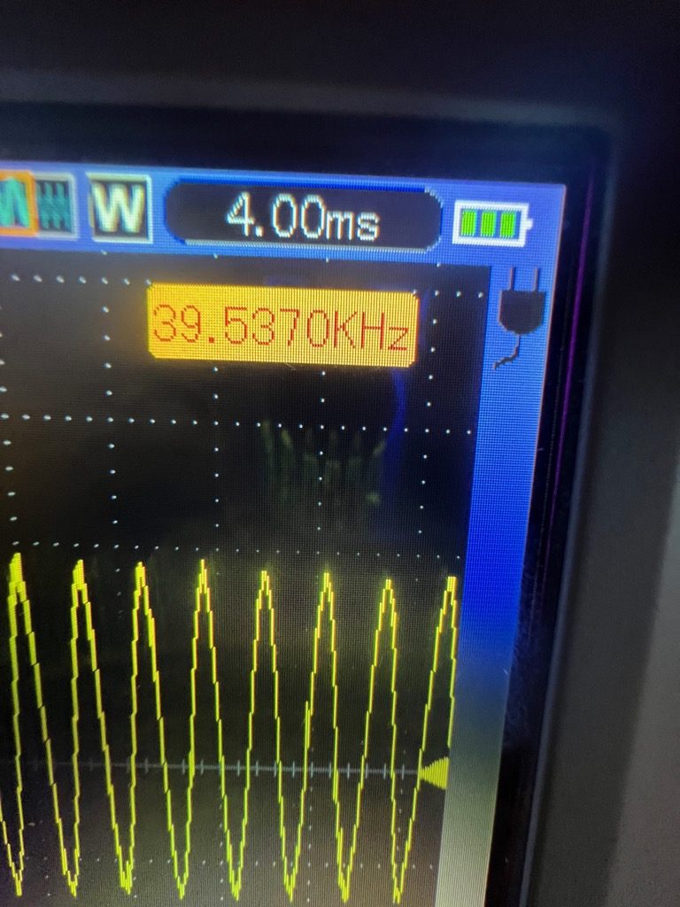
The LM386 IC is a very high-gain amplifier, and should you decide to do these tests I recommend that you plug in the earpiece that comes with the kit as opposed to using the speaker. The gain of my circuit was slightly higher than listed in the course manual. This is not uncommon since the values of components are not tight tolerance so the variables in how the circuit will function are going to vary widely at this point.
My test equipment (and yours) will “load down” the circuit at this point of the build and that is going to affect the values you will see in your circuit. This is normal and if you think it through it is a good thing since you will be both pleased that your circuit is working and that you have made no mistakes or errors in your work.
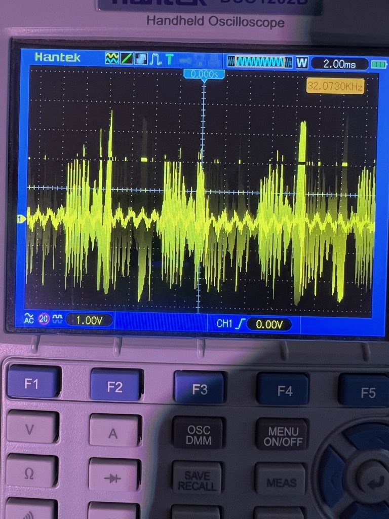
At this point, what you have accomplished is to build a very sensitive audio amplifier and when I was conducting the tests as I placed the probe on test point J3 my body was acting as a large tuning capacitor and I could hear multiple radio stations being amplified through the speaker, and the earphone as well when I plugged it in. Did I mention that using the earphone would save your sanity, keep the dawggies from howling and the cat from climbing the drapes?
 This is all I am going to say about these tests as I can tell you that mine were all well within the specified values listed in the course manual, and in one case higher than listed (Gain) but I did not consider that an anomaly because with a circuit under test it is expected to see values slightly higher or lower than expected normal; in engineering speak we call this the device under test (DUT). As I build more circuitry and add it to the tests along with the test leads and equipment, those higher than projected values will decrease due to the loading of the build. What’s important is that we get values close to the predicted values as we add to the circuit. This is the process of not letting theory get in the way of reality. Theory is great for exploring phenomena that aren’t fully understood or measurable by the acceptable standards and values of the time; but with the advances in technology those discoveries can become useful and better understood. This is what this course aims to teach the beginner.
SECTION 1B THE TRANSISTOR AMPLIFIER
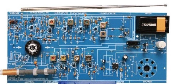
Transistor Amplifier PCB
If you have successfully completed the IC audio amplifier, you are now ready to build the five-transistor audio amplifier. The transistor audio amplifier is built on a separate Printer Circuit Board (PCB) and will plug into the IC socket. It will be necessary to remove the IC from its socket. The ratio of the power delivered to the speaker and the power taken from the battery is the efficiency of the amplifier. In a Class A amplifier (transistor on over entire cycle) the maximum theoretical efficiency is 0.5 or 50%, but in a Class B amplifier (transistor on for 1/2 cycle) the maximum theoretical efficiency is 0.785 or 78.5%. Since transistor characteristics are not ideal, in a pure Class B amplifier, the transistors will introduce crossover distortion. This is due to the non-linear transfer curve near zero current or cutoff. This type of distortion is shown in Figure 12 on page 15 of the course manual.
In order to eliminate crossover distortion and maximize efficiency, the transistors (Q11 and Q12) of the audio amplifier circuit are biased on for slightly more than 1/2 of the cycle, Class AB. In other words, the transistors are working as Class A amplifiers for very small levels of power to the speaker, but they slide toward Class B operation at larger power levels. Transistor Q10 is a Class A amplifier that drives Q11 and Q12 through the bias string R46, D5 and R49. Q13 and Q14 are current amplifiers that amplify the current of the transistors Q11 and Q12.
The AC and DC gain are set by the DC current in transistor Q10 and the collector resistor R46. The AC gain of the Audio Amplifier is approximately equal to 100, while the DC gain equals approximately 50. The transistors Q13 and Q14 are self-biased so that the voltage at their emitters is approximately 1/2 the supply voltage. R47 provides feedback to the base of Q10 which is biased at approximately 0.7 volts. Capacitor C40 couples the audio signal from the volume control to the input of the audio amplifier. Capacitor C43 blocks the DC to the speaker, while allowing the AC to pass. (See text and figures 12 and 13 from page 15 of the course manual)
In the first section, the integrated circuit (IC) U1 was built, tested, and proven to work with all pertinent values listed. This next section will involve building the transistor equivalent of this circuit, it will then be tested and the measurements compared to the ones taken I the first circuit.
The transistor amplifier is built on a separate PCB, and this is then mounted in the same socket as the U1 was mounted in and the measurements taken from the same circuitry that is installed on the main PCB as before. The objective here is to see the comparative values between the two types of circuitry to amplify the radio waves being detected.
SUMMARY
If you want to get deeper into radio theory and construction with hands-on learning this is the kit for you as it is a starter-level course that costs far less than going to a technical school or university. If you are a rank beginner it is going to be a serious challenge for you. And even you have experience, it will challenge you to grow. A beginner should find a ham radio club and ask the members there to help you with the build, even if you don’t want to know all the theory and just want to build the kit there are some issues in the kit that a good local ham club can help you work out.
In a recent article, I reviewed an AM radio-only version that is much friendlier to a beginner and easy to complete. The skill set one can learn from this build is something that will be valuable in TEOTWAWKI and even just to have available for current use. Skill is the ultimate barter, even when there may be good currency (gold & silver) your ability to trade skill for food, wood, seeds, things that are needed to sustain life, that is true barter.
There are errors in the formulas in the course manual, and some of the test procedures are confusing even for me, but if you just think them through and do as I did make a list of step-by-step methodology to document the tests, then they do eventually make sense.
Recommended kit completion tool links:
- Tool Kit (Includes a DMM)
- Flush cut wire cutters
- ESD Pad, with Static Strap
- Rosin Core Solder 0.8mm
- Solder flux liquid
- Third Hand Soldering Station
Some Final Notes On Tools
The helpful Third Hand Soldering Station frees your hands for safe soldering, gluing, positioning, fastening, and assembly of objects small to large in size for tasks requiring a high level of precision, such as avionics. This soldering helping hand is equipped with a 2x magnifying glass on an adjustable arm to perform precision work on even the smallest of objects or workpieces. With this tool, you can achieve near-perfect results. It may be too small for this project but can be used on other projects.
 A DMM (a basic one is included in the tool kit) is a really useful tool for solving industrial and household electrical issues. Suitable for testing Household Outlets, Fuses, Vehicle Batteries and Alternators, Automotive Circuit Troubleshooting, Off-Grid Battery Charging Systems, small battery testing, et cetera.