


(Continued from Part 1. This concludes the article.)
Back to First Principles
What would be really useful would be a series of lights which would reflect how full the tank was, and if in addition to that, an audible alarm for high water-level. Perhaps I could build something like this using basic off-the-shelf electronic components and my rather rudimentary knowledge?
Like most reading this, I am no engineer, and no electrician. My only personal asset seems to be that, I like to tinker with stuff. So, I dug out the multimeter and an old breadboard and began to experiment. To save time for others who are trying to solve a similar problem, a description of what I finally concocted follows.
I ended up using five NPN transistors (BC547), as shown in the schematic diagram below as having the arrow pointing away from the base towards the emitter.
Transistors have three pins: collector, base, and emitter. A transistor acts as a solid state switch turning on with a positive voltage applied to the base. To figure out which pins are which, refer to the spec sheet that came with the transistors. The BC547’s I used came in what is known as a TO-92 package which, with the flat face up, leads towards you, left to right: collector (1), base (2), and emitter (3).
By creating my probe using a fiberglass rod, I placed six bands of copper, at the bottom and at 9 inch intervals. The bottom band was wired to the plus (+) power supply. At heights of 9, 18, 27, 36 and 45 inches each was wired to the base of an NPN transistor through a 330 ohm resistor.
The fiberglass rod itself was salvaged from left-overs from a six-foot-high chainlink fence project. It turned out this was the perfect length for covering the depth of this cistern. Bands of copper were created using strapping of the sort used by plumbers. Stainless steel machine screws were used to attach each copper band to a soldered terminal connector on each level wire – six wires in total.
Each emitter of each of four NPN transistors connected directly to a green light emitting diode (LED). The LEDs are oriented shown with the bar on the symbol connected to the negative (-) power supply. On my LEDs the longer leads were the negative.
Each NPN collector connects to the positive power supply via a 220 ohm resistor.
For the overflow indicator, I might not always want something that makes noise, so placed a switch on the overflow buzzer, connected in parallel with an unswitched red LED. The red LED will always come on when the cistern is close to being full – the buzzer can be switched off.
One additional LED, yellow, indicates that the power supply is on. So, even when the cistern is empty a working device will always show yellow.
I started out using a 9 volt DC regulator (LM7809) to power the circuit. In my small tank circuit testing, 9 VDC was sufficient. But, I subsequently determined via trial and error that a 12 volt DC regulator (LM7812) was more appropriate for the cistern application. The DC voltage regulator allows this device to be powered by my solar panel battery system which runs 23vdc through 30vdc.
The tab of the voltage regulator LM7812 on the table extending out the top, the pins towards me, left to right, are input (1), negative/ground (2), and output (3). I supplied DC from my solar power system battery, nominal 24 vdc (+) on the input pin 1, 12 vdc (+) available on the output pin 3 connected to the water level circuit, with the negative conductor from the 24 volt battery (-) tied to pin 2.
The next question I needed to settle was how much of a heat sink would I require on the LM7812? With the tank full, I measured a maximum power consumption of 6.5 watts, translating into roughly half an amp of current draw at 12 volts. The spec sheet for the LM7812 rates the max current at about 2 amps if adequately sunk. Therefore, I figured that not much of a heat sink would be required.
After developing a working circuit using the breadboard, it was assembled on a 2”x2” perf board which was mounted on stand-offs inside a 2” x 3.5” x 2.5” plastic utility box designed for an AC receptacle, with customizations to the box and cover plate. I have two miniature toggle switches: one to shut off the input power; another to shut off the audible alarm.
The following four photos depict testing and installation.
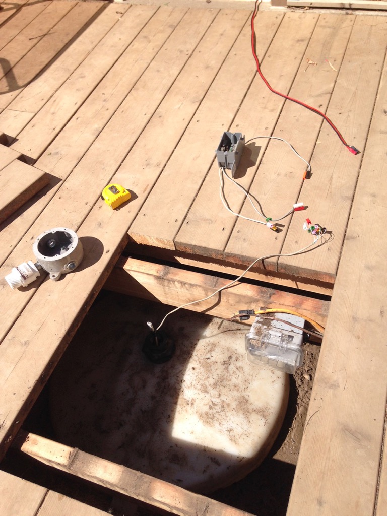
Figure 1: In situ testing of the sensor prior to final assembly.
I used Anderson Power Pole (APP) connectors in six colors for signal, plus two colors for power. The APPs allow one to be able to take the experimental circuit in and out easily.
At the top of the cistern, I threaded a Crouse-Hinds octagonal utility box, using a short 1/2” NPT nipple.
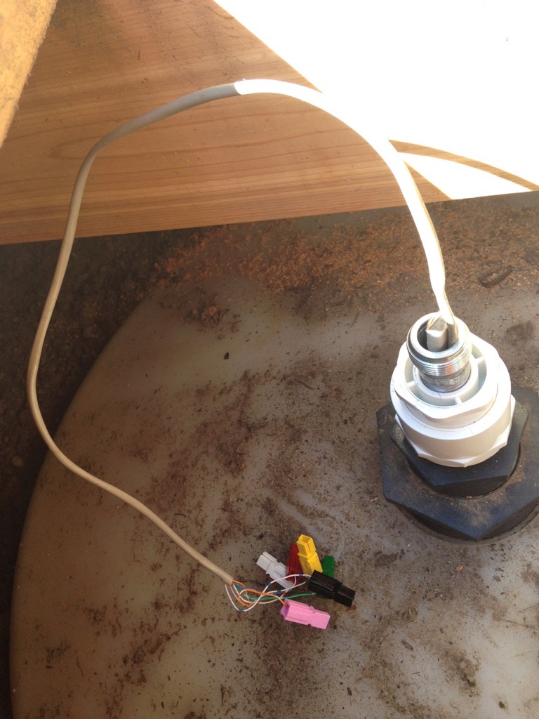
Figure 2: Vent in cistern adapted down to 1/2NPT nipple.
The six-conductor weather resistant cable running between the circuit ultimately installed indoors, and the Crouse-Hinds box at the cistern, was secured using a weather resistant compression style connector. A custom screened vent was affixed to the other side of the box, as we need to ensure that we aren’t creating pressure or vacuum in the tank. The fiberglass censor rod runs up through the nipple and joins to the weather resistant cable via the color coded APP connectors.
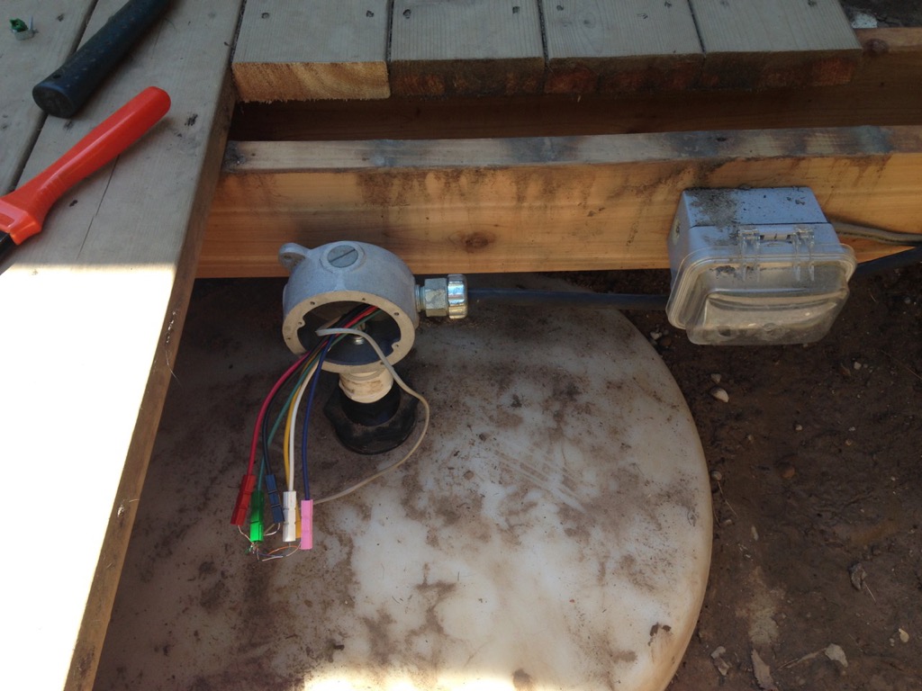
Figure 3: Crouse-Hinds diecast octagonal electrical box threaded in place.
All of the components, with the exception of the APP connectors, were readily available at local electrical and electronics jobbers. The Anderson Power Pole connectors came courtesy of a local ham radio operator.
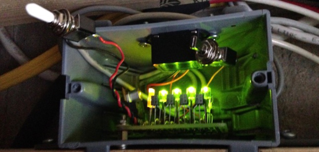
Figure 4: Full cistern shown by four lit green LEDs.
Troubleshooting
There was initially an odd instability in the circuit, in that the overflow buzzer came on with bright LED lights when cold. After a while, the LEDs became dimmer and the buzzer became inaudible. I attempted to address this instability by adding the 100 microfarad capacitor on the input of the LM7812, and another on the output side, reflected on the schematic below. After four hours of initial testing, the voltage regulator temperature was measured to be 85F and stable.
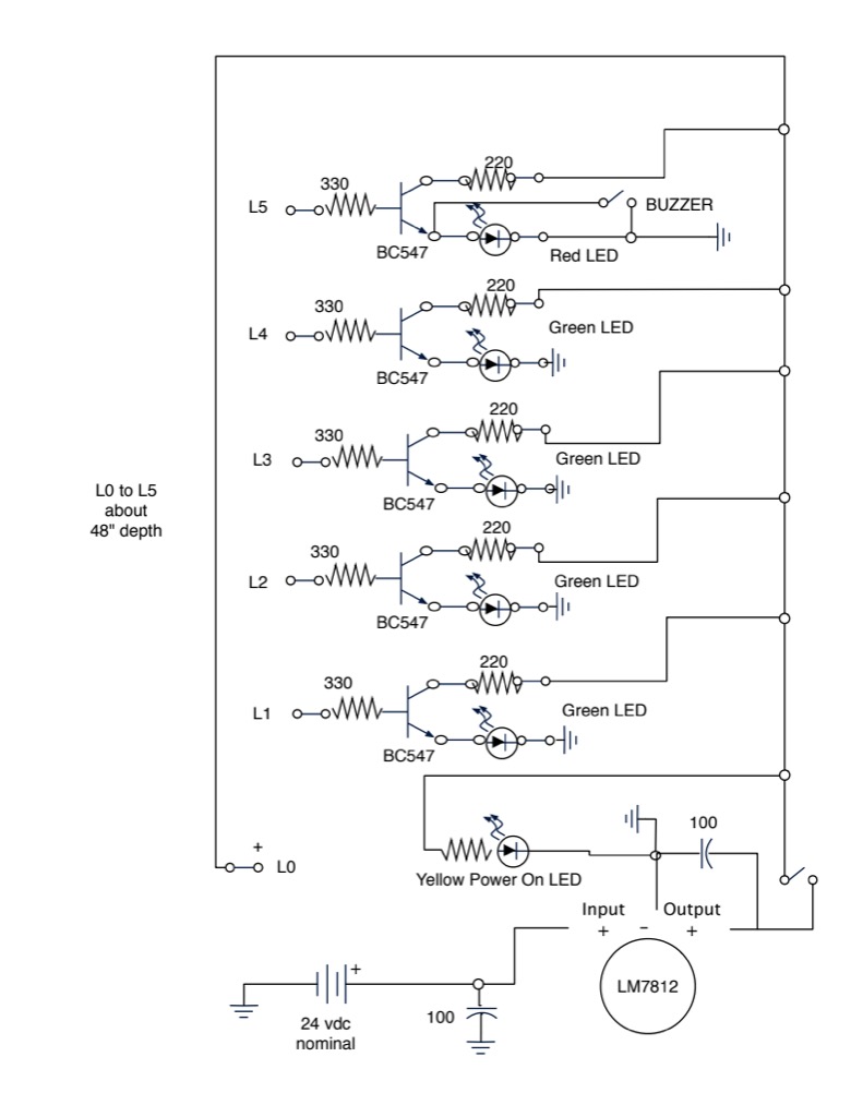
Figure 5: Schematic of water level monitoring circuit now in use.
After many months of operation, the circuit has worked reliably with the exception of the buzzer. While the buzzer worked normally for the first few months, in recent weeks it has barely let out a squeak. Since I have moved on to other projects, I have not chased this problem down.
Conclusion
I would again draw your attention to the quotation from The Civil Defense Manual, which appeared near the outset of this article, in Part 1. Water is essential to life. It is your fundamental ‘prep’ item. We need to be taking this seriously.
In this article, we have supplied some baseline data based on our experience after being suddenly shut off. Also, we devised a methodology for monitoring water usage. The simple schematic diagram below has been provided to get you started.
We have been exclusively using the cistern water since February 2024. We finally installed the water level measuring system in June. At the point of this writing, we have used it successfully.
How linear is the water measuring system? The stated nominal capacity of the tank is 1150 gallons. The cistern is not a perfect cylinder. Empirically, experience has shown that there are roughly 200 gallons between empty and each green LED marker. The top final red LED reflects an additional 200 gallons, a full tank. There remains a bit of airspace at the very top.
We are now able to have water storage status in real-time. The water level circuitry and the cistern pump are both powered by our solar backup power system which provides the desired level of independence from the grid.
Realistically, this water storage represents less than two months supply for the two of us, if a reasonable water conservation methodology is prioritized. It would be rather stressful if circumstances required us to stretch this out. On the other hand, experience has also shown that without rigorous water conservation, we can easily go through this amount in less than a month.
The arrival this past summer of our daughter with her four-person family ensured that we consumed most of the stored 1,150 gallons within ten days. Good thing we had 500 gallons still stored in the IBC totes in the garage from spring. These totes smelled of old algae from last summer, an odor and taste which did not quite filter out. This unfortunate fact helped conserve usage.
This recent summer with the cistern we did manage to stay ahead of the algae bloom. How we managed to control algae this summer, could be covered in another article.
The timing of a SHTF event will not conveniently fall on the day that we have a full cistern. Ultimately, we take confidence in the fact that God has supplied rain in season to his people.