


(Continued from Part 1. This concludes the article.)
Once you have cut, stripped, and made the proper ring terminal connections to the wires, then the next job is to solder them to the various locations as required; this will involve soldering the 6.0” wire and two other wires twisted together as one wire onto the variable capacitor of the kit.
I used a dab of Kester 186 solder flux on the wires before I tinned them and then after I crimped the wires onto the terminals, I put a very small drop of the flux on the crimp connection and then soldered that joint. CML Supply is where you can buy flux. Solder flux makes the soldering job so much easier and helps the solder to flow smoothly into the areas you need it to flow into.

 I also put a small drop of the flux onto the pin-leads of the variable capacitor then applied a surface of solder to the leads before connecting the wires. This is called “tinning” the leads or connectors and is a way of keeping the heating time of the connection short; it also ensures a good solder flow connection the first time.
This kit is as much about learning and developing a skill set as it is about building and learning to use “old school” technology. A skill set that can come in very handy in TEOTWAWKI. Maybe even a bit of barter craft, eh?
Okay, now I’m on page 4 of 9 … and the instructions are going to have me wind the antenna coil, but I have decided to do so something a bit out of order. This kit comes with a beautiful wood base the radio is mounted on. It also comes with two bottles, one with wood stain, and the other a bottle of Polyurethane … I am going to go ahead and stain the board and let it dry before I move on to the rest of the build. There is a sheet of 220-grit sandpaper, so I’ll just smooth out the edges and such and then go ahead and stain the board. As for the polyurethane, it is going to be used to coat the coil once it is wound.
PAGE FOUR OF NINE:
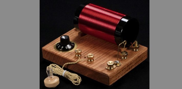
 Steps 1-2-3-4 winding the coil; or otherwise known as “SLINKY TIME”. The coil is the part of the crystal radio that is going to provide the frequency selection and tuning of any radio waves captured by the antenna. It is important that it be wound correctly. This is not a difficult step if you pay close attention to the process.
- DO NOT let a winding of the coil overlap another winding anywhere along the coil assembly. This can induce issues into the radio, and that is something that we do not want to happen.
- Keep your windings as tight as possible. The kit includes far more wire than what is going to be wound around the tube. So let the first end pulled through the tube be long, at least 7” to 8” even though the plans call for a length of 2” to 3” and keep it long.
- Work slowly and steadily; my hands got tired mainly due to my age and physical condition. But you can do this and do it well. Once you reach the other end of the tube you will find some extra wire if you get the same length of wire as I got.
When I first took the wire wound around the loop, a part of it fell open onto the floor and looked exactly like an old slinky toy, do you remember the slinky right? (How about the old joke about how slinky and politicians are alike? They are mainly useless but fun to watch falling down the steps.) Well, this is one slinky you want to try not to open and work with when your baby kitten is in the room. Please trust me when I say this is just a disaster waiting to happen.
 I then put a coat of polyurethane on the completed coil assembly after I had determined that it was wound as tightly as I could get it, and that none of the individual loops of wire overlapped another loop. I let it set overnight to completely dry and cure out.
Now that the coil assembly is done, the rest of the build is a matter of installing the various screws and nuts to the connectors of the wires are attached to. The instructions in the directions are very clear and easy to see in the photos and follow.
I hooked the ground wire connection into the copper wire ground we have in the workshop; this copper wire leads along the wall, exits the building and is clamped to a copper rod run down into the ground. I have a lot of radio and test equipment in my shop, so a good solid ground is needed.
 I ran a thin 26 gauge insulated wire from one end of the room to the other, about 30’ or so and just draped it over a rack and attached it to the ANT terminal on the opposite side of the coil assembly that had the ground connection. I didn’t expect much of a signal since my building is a metal shop, but to my surprise the local AM station (660 AM KFAR) came booming in. Well, “booming “ may be a bit of an exaggeration, but it did come in nice and clear.
What I found interesting is that if I sit in my pickup truck parked just outside the shop near our building the noise from the electrical grid in this area almost totally overpowers the same signal with static. Yet on the inside using my 1N34 diode crystal it was clear? I’ll need to figure out why. For now, I am happy that this kit worked and that the technology discovered in the early 1900s is still alive and well.
I hope you have enjoyed this article and maybe consider buying a kit of your own. There are many out there on the market, just one word of caution: the earphones used are “old” type earphones, modern new ones will not work, and the market is being flooded with knock-off ones made in China that are junk. They just do not work.
By the way, any kits that may be “vintage” originals might not work either because they are made form a sodium-based crystal material and age may have caused that crystalline structure to decay.
My next project will be a one-tube simple AM kit / project that can be built from scrap materials and use a battery for power. I reviewed a kit from another radio project that was published in this blog, but this next design will be aimed at a superheterodyne type of receiver that can run on almost no power at all yet receive radio signals quite well; and use modern earphones.