DISCLAIMER: USE THE INFORMATION PRESENTED HEREIN AT YOUR OWN RISK. HIGH VOLTAGE DIRECT CURRENT, SUCH AS DESCRIBED BELOW, CAN BE LETHAL. IN ADDITION, EVEN SMALL GEL-CELL BATTERIES CAN PRODUCE HIGH CURRENTS WHEN SHORT-CIRCUITED AND QUICKLY MELT WIRE, DESTROY COMPONENTS, AND START FIRES. IF YOU ARE NOT FAMILIAR WITH ELECTRICITY, THEN ASK SOMEONE QUALIFIED TO CHECK YOUR WORK BEFORE ENERGIZING ANY OF THE CIRCUITRY DESCRIBED.
Older vacuum-tube radios are popular in the prepper world (and rightly so) for their resistance to EMP damage. One useful fact about them that is often unrealized is that many of them can be powered by direct current directly from batteries, without the use of an inverter to make 120VAC.
The All-American Five (AA5)
Many communities in the early twentieth century had 120V DC power, instead of AC. Many radios from the 1940s to 1960s were designed to work off of either 120V AC or DC power, and are of what was commonly referred to as the ‘All-American Five’ design, so-called because they used five vacuum tubes. The earlier designs used large octal tubes (50L6, 35Z5, 12SA7, 12SQ7, and 12SK7) and the later designs used seven-pin miniature tubes (12BA6, 12BE6, 12AV6, 50C5, and 35W4). These sets were designed to have their tube filaments powered directly off of the power line with no transformer required. (The first digits of a tube’s number, that precede the first letter, indicates its filament voltage. Note that the tube prefixes, when added together, add up to 121). Further, the circuitry was designed to run off of a relatively low plate voltage of 120V. This allowed a simple inexpensive design that would run off of either AC or DC power.
There are some variations on this. Later AM/FM radios used a solid-state rectifier to produce the plate supply DC, and used the now-eliminated rectifier tube filament voltage drop for an FM converter tube, to allow the set to receive the FM broadcast band. Some just replaced the rectifier tube with a solid-state rectifier and used a resistor to provide the voltage drop for the filament string. The venerable Hammarlund S-120 uses this system.
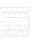
Many prepper locations have solar panels that commonly output 12VDC nominal, or greater than 13V in good sunlight, depending on load. I procured ten 12V 2.2 ampere-hour gelcell batteries and a twenty-pole double-throw rotary switch, and built an arrangement whereby I can easily parallel the batteries for charging, and then reconnect them in series to produce 120VDC to power my tube radios with the turn of a switch. The switch, while cumbersome, can be found on eBbay fairly inexpensively from overseas military surplus. See Figure 1.
Figure 1
There needs to be a current limiter in series with the batteries to limit charge current when they are deeply discharged. While there are a number of solid-state regulator designs that are much more efficient, I elected to use a simple 12V 36W car taillight bulb in series with the batteries and the solar panel output as a current limiter. This has several advantages:
1. It is EMP proof;
2. It gives a visual indication of charging and the battery’s state of charge (bright at first when the charge current is high, and then dimming to barely glowing when the battery is nearly charged and the charge current is low)
3. It is inexpensive and simple, and its operation is intuitive for a non-technical person to use and repair.
Note that the radio’s power plug is polarity sensitive when operating on DC. It will only work one way – the tubes and dial light will light either way, but the radio’s rectifier will absolutely not pass DC voltage of the incorrect polarity. Mark your radio’s line cord plug with the output connector from the batteries so you can always get it right the first time!
Both my All-American Five and my Hammarlund S-120 consume about .25 amps when in use. With a fully charged 2.2 ampere-hour battery pack as described, it should power the radio for around nine hours.
NOTE: THIS TECHNIQUE ONLY WORKS WITH AC/DC RATED RADIOS. RADIOS THAT USE A POWER TRANSFORMER WILL NOT WORK ON DC, AND WILL IMMEDIATELY BLOW THE LINE FUSE AND/OR BURN UP THE PRIMARY OF THE POWER TRANSFORMER IF YOU ATTEMPT IT.
Farm Radios
Many radios from the 1930s and ‘40s were built for farms that did not have high-line (120V) power. These radios typically used a #6 dry cell for filament power (1.5V), and used a high-voltage B battery (typically 45 or 90 volts) for plate circuit power. The tubes in these radios typically have a 1 prefix, indicating a 1.5V filament – a common lineup is 1A7 – 1N5 – 1H5 – 3Q5. (The 3Q5 has a two-section filament that can be wired in parallel to run on 1.5V, or in series for 3V). B batteries and #6 dry cells are long unavailable, but newer alternatives exist. One or more D-cell batteries in parallel (either alkaline, or preferably, nicad rechargeable) will power the filaments just fine, and nine-volt transistor batteries in series (five for 45 volts, or ten for ninety volts) work great for plate circuit power. These radios are designed for very low power consumption to maximize battery life. You could construct the same switched series-use/parallel charging arrangement as I have described above for charging NiCad nine-volt batteries as well, or just use the 12V gel-cell arrangement I described above to get 120 volts DC, and just use eight or nine 12V batteries in series to get either 84 or 96 volts, either of which will power the ninety volt plate circuit just fine.
The other advantage of many farm radios is they also have shortwave bands available on them, which will be useful in a SHTF scenario to gather information from sources outside of your local area, or even outside the country.
Other battery-powered gear
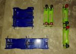
You should have rechargeable batteries for flashlights, Geiger counters, and other battery-powered gear in your BOL. I discovered some really neat stackable D-cell battery holders on Amazon (Sci-Supply LC2015 Plastic D-Cell Battery Holder) that you can stack together so that you can charge your ni-cad batteries in series easily from your solar twelve-volt system. The AA-cell equivalent is LC20509, also available on Amazon. (I have not found any for C cells yet, at least not on Amazon). Here is what they look like, with two each ganged together in series and in parallel:
While you can charge a single Ni-Cad battery through a current limit from a twelve-volt system, it is much more efficient to series up a number of them so they can charge all at once, and minimize the power lost in the current limiter. Six 1.5V NiCad cells will have a fully charged voltage of around 1.4V each, or 8.4V total in series, and are a great match to charge from twelve volts through a twelve volt light bulb. I use the same 12V 36W car brakelight bulb in a holder, described above, as a current limit between the battery bank and the twelve volt supply. Note that there is not any automatic charge current ‘tapering’ with this arrangement, so don’t leave them on charge too long! A flat nine-volt Ni-Cad battery can be charged in the same way, but a smaller series bulb (such as a parking light or marker light bulb) should be used, for less charging current into the smaller battery.
Newer battery-powered gear
This should go without saying, but any time you buy a cordless tool or appliance, make sure you get one that comes with a car charger, or spend a few dollars more and buy the car charger for it, so it continues to be useful in your BOL.
Power tools with universal (AC/DC) motors
Many older conventional power tools like drills and saws have brush-type universal motors that will run on 120VDC quite well. They were designed to operate on 120VDC for the reason mentioned above under point #1. Due to their higher current draw, you will probably want to use a bigger battery bank (higher than the 2.2 ampere-hour pack that I built for my radios), or live with limited operating time before recharging becomes necessary.
Note that tools with a variable-speed feature, when run on DC, will operate either full-on or full-off, and the variable speed feature will not work. The reason for this is that the variable-speed controls work by triggering a Triac (a solid-state device) either earlier or later in the AC line sine wave, which obviously doesn’t exist with DC current. This may be bothersome, but having a tool that will still work in the fashion is still better than having one that doesn’t work at all.
Powering tools from a battery bank like this may not be as convenient as our now-ubiquitous modern battery powered hand tools, but the older ones are inexpensive, simple, rugged, and most importantly, EMP-proof. I regularly power my 120V saber saw and circular saw with this system if I don’t want to go to the trouble of starting the generator, and it works very well.
Charging battery banks direct from 120V AC power
If you have a generator available and no solar, you can still avoid having to have it running every time you want to use your tools or radios, by directly charging a battery bank which can be used after shutting the generator off with AC/DC equipment. Leave the battery bank in the 120V output mode (if you have the switchable one that I described earlier), or just build a series string of identical-capacity batteries totaling 120V. The input AC power must be rectified to DC with either a single diode (half-wave), or a bridge rectifier (four diodes), which is much more efficient. For your current limiter, a 300W 120V light bulb in series would limit charging current to around 2.5 amps maximum.
Good luck, have fun, and be careful!


Running a hybrid, a combination transistor front end with tube finals in a Kenwood 830 ($300), not sure if I could make the jump to D.C. safely. Because the rig has no mirco chips, or other fine circuity, it is at least somewhat immune to EMP/CME. Enough overload would damage most electrical devices . I do have multiple 400 watt inverters dedicated to this radio stored of course, in Farady cages. Inverters are cheaper than radios.
Simpler is more better, because simple is more reliable, so the rest of the system is 12vdc. I would like to pick up one of the early Kenwood HF sets designed for mobile use that are 12vdc. I would like to know more about those, as if these are transistor only, with no micro chips or gates, then that radio could be a good compromise. I could use several of those. The Yeasu FT-857 is wonderful, yet it may not survive even a weak EMP/CME. Owning multiples of the same tube based radios that can be fixed by the owner is better that the high tech ‘shack in the box options’, unless you can afford to stack those deep. Here is a FT-857 for $600.
https://www.ebay.com/itm/Yaesu-FT-857-HF-VHF-UHF-Transceiver-w-Yaesu-MH-31-Mic-fused-12VDC-Pwr-Cord/383238852297?epid=129710548&hash=item593ad0cec9:g:cEgAAOSwsAtduB1L
Tunnel Rabbit,
Regarding 12 volt HF transceivers, I recommend the Kenwood TS 120/130. Hamfests seem to have better deals than online auctions.
I use this in my mobile and base station powered from deep cycle marine batteries.
Coupled with a tuner and G5RV antenna you can do well, depending on band conditions, voice, CW or digital modes via fldigi.
Do consider the HFSIGNALS qrp rigs, very good radios for only $59 to $120.
Check out AMRRON.
Blessings to you from TEXAS.
TrexTex,
Thanks for the suggestion. The TS-120 is in my price range on Ebay. I’m interested in my own NVIS net using voice at first,that is if I can find anyone who will play. Been trying for years, but can’t find anyone in my area. They are too lazy to get off the repeaters, and keep installing more repeaters without solar back up. Yes, VHF is more reliable, yet the repeaters are not. I’ve been after them to try out NVIS for 6 years. It costs so little, and it is so cheap and easy to set up a test antenna, so why not? Eventually they’ll catch up?
Having a back pack portable NVIS rig would be nice, and that is where the FT-857, and especially the FT-817 would shine. The Lord has provided in many, and in unexpected ways, especially this year. Who knows, it might happen…
Tunnel Rabbit, I use NVIS exclusively for all my HF work. I have an ELK Yagi for 2 meter and 440 and rarely the 220 Mhz bands … I do work digital, some voice and CW for my HF work. I have an NVIS off center fed antenna set up 60 into the top of a spruce tree with the long wire (132 feet) sloping towards the south, and the short wire (90 feet) to the north. I have had great luck with this antenna, and I use a BuddiPole Deluxe for field use. All this and my Elecraft KX3 and 15 watts out on the battery pack … 5 watts if I use the internal battery pack. I wish we could have a net but as far north as I am making it to the outside would be a difficult process … keep trying, look for nets in your area wherever that may be. It took me a while to gain proficiency with NVIS comms and I’m still on the back side of that learning curve but its well worth the effort. This summer I plan to erect another antenna orientated east west as well so I can hopefully get out in the other quadrants. I’m working on my CW as well with my goal of 35 WPM …. keep warm, HF propagation in teh arctic is a challenge …
Glad to get your experience. I need some, but can’t find anyone around here to want’s to play locally… We need a NVIS net around here. Don’t believe we’ll much more than regional comms. It is frustrating to deal with the lack of vision…..If we don’t do it now, we’ll probably not get it done ever. I’ve got a pile of directional antennas, but they still do not go through mountains. Because NVIS goes over mountains, and is very difficult to DF, it is a good tool to have, and costs next to nothing. And if you needed only local, the ground wave will do the trick. Use 160 meters during the day when the D layer is gone, the ground wave might be all that is needed. Few would even monitor 160, especially during the day! Even the FCC can’t DF that! This is what is secure commo, the cheap and easy way. I guess most folks need to learn the hard way, if they will learn at all….