One of the distinguishing features of traditional Ham radio, particularly shortwave (high frequency or “HF”) Ham radio, was that you generally had to literally make your own antenna. You could purchase transmitters, receivers, transceivers, microphones, and even Morse code keys, but you likely had fabricated at least one wire antenna. In the event of a national disaster, many people may wish to have effective HF communications for medium- or long-range communications, and they may be faced with the need to construct an antenna. Other forward-thinking preppers may wish to gain Ham radio licenses and experience in HF communications and need to put up such an antenna right now. This article will explain two simple antennas.
Resonant half-wave dipole
The easiest antenna to make at home is a resonant half-wave center-fed dipole.[1 [1], 2 [2]] This antenna’s length is selected to work well on one Ham radio band, with an acceptable standing wave ratio (SWR) over about a total bandwidth of about 3% of its center frequency, which is usually enough. It may also work acceptably on the 3rd harmonic frequency. Hence a 7MHz dipole (40 meters) may function acceptably on 21MHz (15 meter Ham band).
Unfortunately, a bit of trial and error is needed to make a resonant half-wave dipole. There are just too many things that can affect the actual resonant frequency for any length formula to be guaranteed. You will need an SWR meter (or alternatively, an antenna analyzer, which is a much more expensive instrument) and considerable patience.[3 [3]] The first trial length to use is: total length in feet = 468/(frequency in MHz). For example, an antenna made for 7.2 MHz would have a total length of 65 feet. Add a few inches for loops to connect to both center and end insulators for mechanical support. Cut your wire in half (each end is now 234/frequency), and insert a center insulator [4] in the middle. Insulators can be fancy commercial glass or plastic ones, or simple pieces of suitably heavy PVC, plastic, or even paraffin-soaked wood, about 3″ long and 1″ wide with a hole drilled or punched a half-inch from each end. They just have to be reasonably strong, and non-conductive! Run a wire end through the hole and wrap or tie it back onto the wire. You don’t have to solder the wrap on the end-insulators. You do have to connect your transmission feed line’s two conductors, one to each half of your antenna, at the center insulator. Most people use coaxial cable transmission line [5] to feed this sort of antenna, usually 50-ohm RG-58A/U or similar. (This is because the antenna will have a center characteristic impedance near 50 ohms, and the transmitter output impedance is usually 50 ohms also, so power flows smoothly if the coax has the same characteristic impedance. This impedance is simply the ratio of the voltage to current of energy flowing through the lines.) Solder the shield to the wire on one end of the center insulator and the center conductor of the coax to the other. Be careful not to melt the coax insulation and short it out. (Using pliers to create a heat block is helpful). If you can’t solder, you could try crimping the connection. If you need this antenna to work for quite a while, dab dielectric grease [6] or some other non-conductive water repellant on the exposed portions of the coax at the center conductor.
Pull the antenna up to your desired height using suitable ropes. Do not use the coax to pull the antenna up; you’ll rip the dainty coax conductors. It really isn’t important whether the antenna is sloping or even V-shaped (either up or down) within some reasonable limits. If the antenna is more than half a wavelength high above ground, it will send more energy toward the horizon (favoring longer distance contacts). If the antenna is lower, at 0.1-0.2 wavelengths height, it will tend to send more energy nearly straight up (favoring contacts a few hundred miles away).
Now the fun begins. Chances are good that your SWR will not be a beautiful 1:1, or even an acceptable 2:1, at your desired frequency range. One can use trial and error, cutting or lengthening the antenna until success is achieved. (Reasonable lengths can be added to each end by simply twist-connecting them at the end and allowing several inches to simply drop downwards. It works!) A more calculating approach is to move to the lowest legal frequency (on the desired band) and measure the SWR, then to the highest frequency (on that band) and remeasure the SWR. Depending on which is better, you now have a clue as to whether you are too long (better SWR at lower end) or too short (better SWR at higher end). I can, well, remember tediously measuring an antenna to the nearest 1/16″ and then finding it was feet off of resonance! When you are way way off, the SWR is terrible at both ends of the band, and the best thing to do is to add or subtract 2-3% of your length and try again.
Additional half wave antennas can be connected “in parallel” at the center insulator; use creative supports so that the wires don’t tangle and achieve two feet or more separation at the end of the shorter antenna. Google this for more information.
Non-resonant antenna/tuner
A slightly more complicated but ultimately more versatile antenna, which can be constructed in perilous times without any commercial supplies other than a SWR meter, is a non-resonant horizontal dipole antenna with a very simple L-network antenna tuner. Commercially sold antenna tuners are usually fancier, using Pi- or T- networks. (The letter designation is to indicate roughly the configuration of inductors and capacitors when drawn in a schematic.) These tuners are generally able to match just about any random piece of wire acceptably. If you have a commercial antenna tuner [7], or can get one, they will work very well. If you can’t, a homemade L-network is not as versatile, but it is easy to build! An accompanying schematic shows that the L-network has only two components: a variably-tapped inductor and a variable capacitor.[4 [8]]
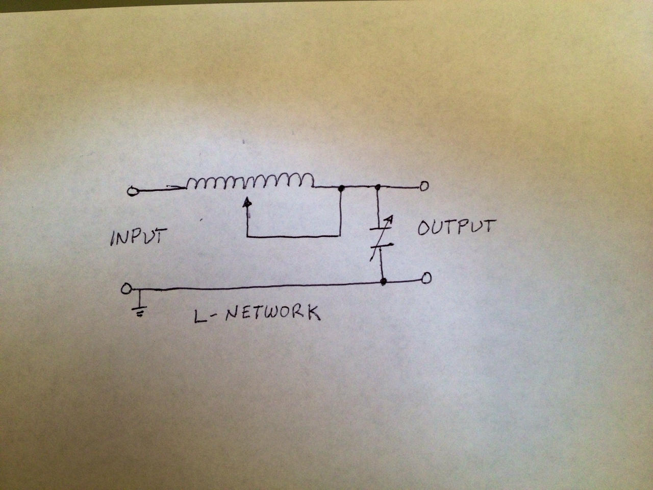 [9]
[9]The Antenna
The antenna is a horizontal (or sloping, if need be) dipole just as above, with one proviso: its length must be longer than a half-wave dipole would be for the lowest frequency desired. Avoid trying to run a short antenna. This is because shorter antennas have lower radiation resistance and one can end up with very inefficient results where huge currents are flowing in lousy transmission wires and wasting a considerable amount of the available transmitter power before ever reaching the antenna. It doesn’t even have to be a dipole with equal halves. In a pinch, you can use just a single long wire, longer than half wavelength, and use a grounded wire as the other half of your antenna.
Transmission Line
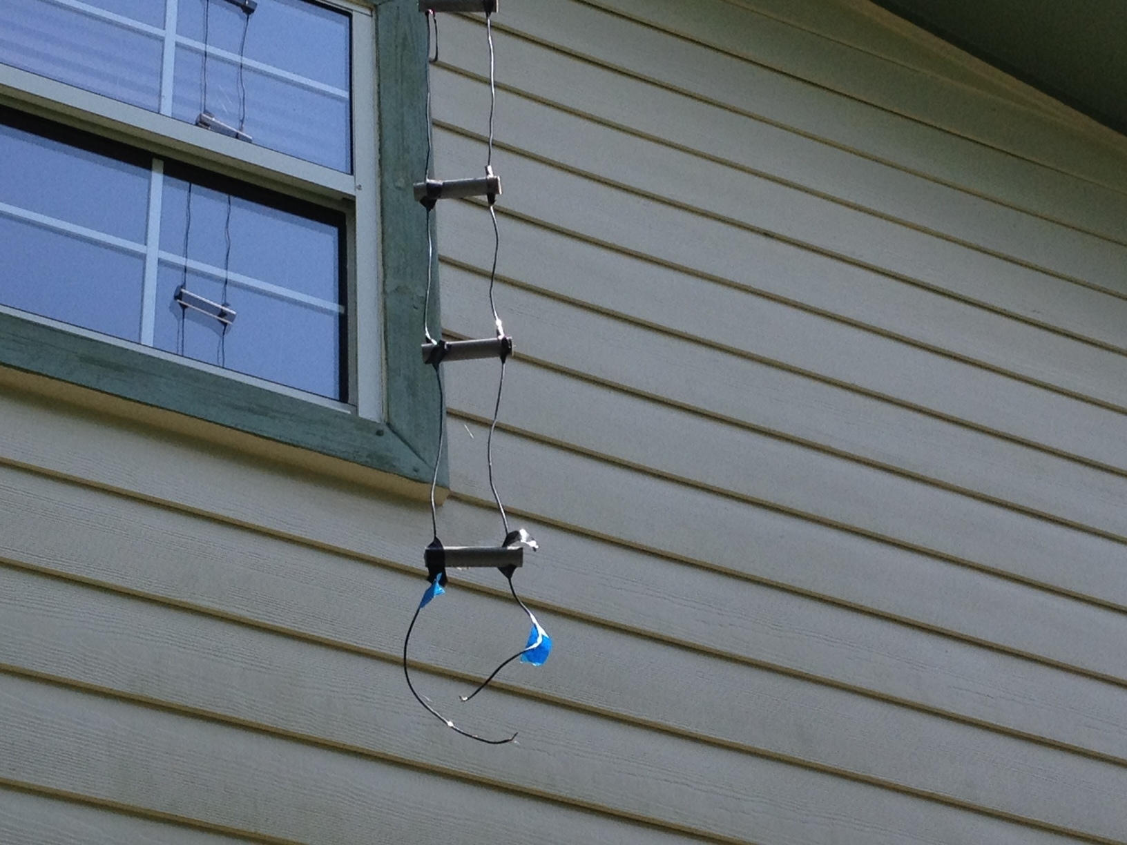
Coax is expensive and will likely have high losses or even develop destructive arcs at various matching situations when used with a non-resonant antenna. I don’t recommend it for use with a non-resonant antenna. Simple “ladder-line” transmission line consisting of two wires held a couple of inches apart (like railroad rails) can be used to very efficiently get your transmitter’s power up to the antenna. (You can even use 300-ohm TV ribbon transmission line with good outcome at lower powers, say up to 100 watts.) Try using wire of at least 16 gauge and preferably 14 gauge. Insulated wire is a bit preferable. Use a spacing of two to three inches, maintaining your chosen spacing by using “railroad ties” made of non-conductive 1/2″ PVC short stubs with two holes drilled and the transmission line threaded through them. It ends up looking just like a ladder or a railroad line. The PVC pipes should be spaced about every 6-12 inches, and can be secured either by relatively tight holes, or a bit of insulating black electrical tape [10], or even a string tying the wire to the PVC. While it looks inexpensive, this sort of transmission line has virtually zero loss, and unless your wires lose all their spacing, is unlikely to ever have a flashover arc!
 [11]
[11]Here’s some nerdy stuff for the more electrically-minded reader; this sort of air-insulated ladder line will have a characteristic impedance of a few hundred ohms and will be horribly mismatched to the antenna, but because the conductors are hefty and the insulator (air) has virtually zero loss, as long as you can get a “match” with your matching network, virtually all of your transmitter power is going to end up getting radiated!
Constructing the L-network Tuner
First, make a variable-tapped inductor. Wind about 40-60 turns of 14-gauge solid wire around a 1 1/2 inch PVC pipe or wooden (not metallic) cylindrical support. Bare wire would be best, but space the wire out a bit so the adjacent turns don’t short out and so you can grasp individual wires with a small alligator clip. You can use co-wound string to set the spacing and then remove it, and you can maintain the spacing with some epoxy glue drizzled along the bottom. Connect a flexible wire to one end of your homemade inductor, and use an alligator clip to allow the ability to short out (and hence electrically remove) any desired portion of the inductor. If you used insulated wire, cut off the insulation along the top edge of your coil so you have a place to connect the alligator clip.
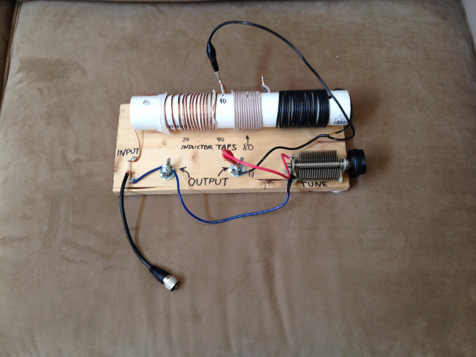 [12]
[12]The Variable Capacitor
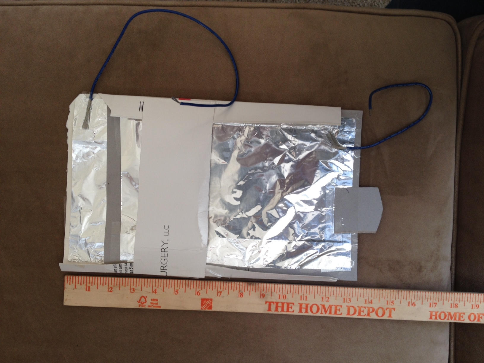
If you can find a variable air-gap capacitor of roughly 250 or so picofarads, that will do for the capacitor; connect it as in the accompanying schematic. You want an air gap of at least 0.01 inches (the thickness of three sheets of paper), or you may have flashover arcs at times. A gap of .02 inches is better. If you don’t have such a capacitor, you can actually make a suitable capacitor by taping about 8×10″ of aluminum foil [13] to one side of dry cardstock or thin cardboard, taping a wire to it, and affixing another 8×10″ of aluminum foil to a fixed piece of heavier cardboard, and a wire connected with tape. With the cardstock kept between the two and sliding the top foil variably over the bottom, you have a fine variable capacitor! I did this as a teenager, and it worked well. Arrange for the wires to be 12 inches or less for acceptably low wiring inductance in the HF bands. An accompanying photo shows a homemade aluminum foil sliding variable capacitor that adjusts from about 40 pF to 500 pF.
 [14]
[14]Adjusting your homemade L network will require some patience. Keep notes once you find settings that work. Start with your transmitter set for a lower power, so that it can remain on for 5-10 seconds of time without damaging the final amplifier. First set your variable capacitor about 20% overlapped, and successively try shorting out variable portions of your inductor from none to all, seeking the setting where the reflected power on your SWR meter is minimized. (Remember the forward power is probably also changing.) Once you find a possible reflected power null, try adjusting your variable capacitor for a better (lower) SWR. Then jockey the inductance a bit and re-vary the capacitance. Avoid touching bare metal on either the alligator clip or the variable capacitor; otherwise, you may get a shocking or burning surprise! If you get the SWR below 2:1, you’re in good shape!
It is always possible that your combination of antenna length and L network will simply not allow a successful low SWR on one certain frequency, and you find it impossible to get an SWR below 3:1. In my experience, this is rare. However, simply remove or add a few feet from one or both ends of your antenna, and it will likely start to work! (In some instances, you may end up connecting the variable capacitor on the input side rather than the output side.)
Once you find a solution that works, you can cautiously raise your transmitter power, looking for any sign of arcing on your variable capacitor. If you’re unlucky and you have an arc, simply reduce your power below where it happened. Using a slightly different tap on your inductor may also help.
After your have found adjustments that work on each of your desired bands, mark them or even solder in fixed “taps” on your inductor to make it easier to quickly connect to them. To move from one of a particular band to the other may take a small adjustment in your variable capacitor or even a turn or two adjustment in your inductor tap.
Your friends will be amazed that you could make a working multi-band antenna with little more than wire, PVC pipe, a bit of tape, and aluminum foil!
References
[1]ARRL, Single Band Dipoles [15].
[2] Healy JW. Antenna Here is a Dipole [16].
[3]PrepperDoc, Understanding the Radio Shack SWR & Power Meter.
[4] An example of a really high-power L network: KC5LDO, L-Network Tuner [17].