


I consider the ability to communicate in a TEOTWAWKI scenario, and being able to obtain information outside the immediate area, critical. HF communication best fills this need. I had the radios but needed an antenna that would work on most amateur bands and others if needed. Having recently relocated to a more free state, I had all the real estate to put up whatever antenna I wanted. I wanted an antenna that fit into the space of a dipole, is relatively invisible, easy to build, and can be coax fed. The need to bury the cable ruled out a ladder line and tuner fed, all band antenna. A remote tuner was also out, since it added a potential point of failure.
My search of the Internet led me to the OCF (Off Center Fed) antenna design. An OCF antenna is similar to a dipole, except that it is not fed at the center but at a point offset from the center. This offset gives the antenna the multi band capability. This article as well as this one best explain how and why this type of antenna works on multiple bands. Unlike Terminated Folded Dipoles and End Fed Inverted V antennas, an OCF antenna works on multiple bands but not on all frequencies. The benefit of this is that the OCF antenna is much more efficient in getting the signal in the air, rather than heating the terminating resistors, like on the other two antenna types. A properly tuned OCF also does not require the use of a tuner.
This article describes how I built a multiband OCF antenna, including the actual dimensions, measurements, and some performance information. While primarily designed for the 80/40/20 meter bands, this antenna also works on 17/12/6 meters. The article is geared towards people new to antenna building, so it may seem redundant or lengthy to old timers. There are several vendors that sell ready-made OCF antennas, but I wanted to build my own, so I would know how the antenna is put together and how to repair the antenna in a SHTF scenario, in case it gets damaged or wiped out.
Antenna Design
There are two OCF designs on the web that had been tried and tested. One is fed at the 20/80% point and one fed at the 36/64% feed point. The offset percentage refers to the percentage of the wire that is connected on either side of the feed point. The 20/80% design is described in one of the previous links. The 36/64% design is described in this article . The 36/64% fit my needs and space the best.
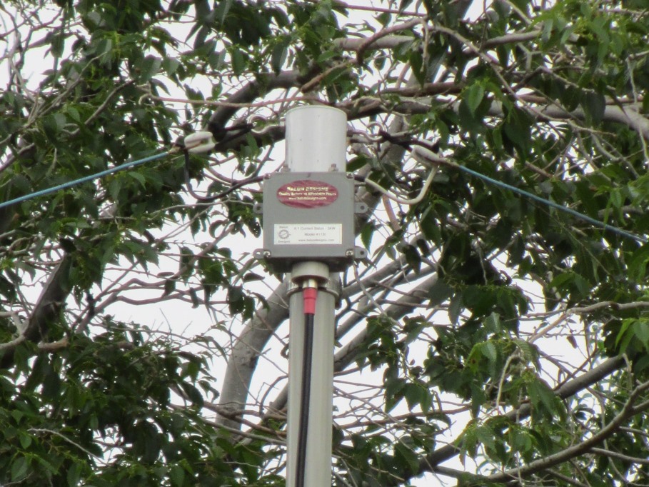
A good quality balun (transmission line transformer – BALanced to UNbalanced) is required for the antenna to work properly and to match the impedance, which is higher than that of a resonant dipole. For lower antenna height, usually below 40’, a 4:1 ratio is recommended; for higher antennas, a 6:1 ratio is recommended. I had a 4:1 current balun (Balundesigns 4113) from a different project, as well as a large reel of sky blue 14ga XHHW stranded copper power wire. This is what I used for the antenna. (I have 14ga solid copperweld as backup, in case the copper ever breaks). The center mast was fabricated from telescoping fiberglass tubing and hose clamps. This way the mast could be easily lower if needed.
Initially, I cut the wires to 85′ 2½“ and 47′ 9½”, as stated in the instructions. (This is longer than the calculated length, which turned out good in the end.) Actual antenna length can vary significantly depending on elevation above ground, ground conditions, nearby objects, et cetera. It is easier to cut a long antenna than to add wire later!
I stripped 6” of the wire at the balun ends and wrapped and soldered the wire around small ceramic egg insulators. (These are inexpensive from e-bay.) I attached those to the center support (to the mast, not balun) with Dacron antenna rope. Be very careful not to nick the copper conductors when stripping the wires, or they will break at a later time. The connection between the balun and antenna conductors was made with some extra flexible 12 ga. extension cord wire to prevent breaking due to wind flexing. If you don’t have any insulators, you can fabricate some from plastic, or even use the rope as insulator. All wire connections were soldered. I loosely attached the wire ends with Dacron rope and pulleys to the end supports to allow trimming the ends as necessary.
The center support and balun were installed on top of the telescoping fiberglass mast at 26 feet using four DX engineering telescoping fiberglass mast sections (8 feet each) and their hose clamp mast kit (could not afford more mast after buying my retreat!). The hose clamp kit makes it easy to lower the mast if future repairs or changes need to be made. It also allows lowering the mast to make the antenna “disappear”. Guy ropes at the 22 foot level protect the mast during strong winds. All balun mounting components, brackets, and so forth were made from PVC pipe, pipe tee’s, and PVC scraps. (The tree in the picture is actually 40’ behind the antenna.) All hardware was stainless steel. The bottom mast section was buried 3’ for support and stability. I used a level to get the bottom section perfectly vertical.
Each end support is located 90’ from the center support (in case the OCF didn’t work and I needed to revert to a dipole). The end supports are two 12’ pressure treated 4×4’s, buried about three feet deep. This leaves the antenna ends 9’ above ground. The buried sections of the mast and end supports were wrapped in PVC pipe wrap tape for added protection. The ground conditions at my location are loose, volcanic soil. Installing the mast and end supports was surprisingly easy using a post hole drill. For reference and comparison, the orientation of the wire is directly east (short wire) and west (long wire). The elevation is at 7300 feet in open, lightly treed country. Due to the distance from the mast to the end supports, this antenna is more of a flat top than an inverted V.
The feeder from the house to the antenna is DXE400MAX (LMR400 equivalent) coax. Although the cable is direct bury rated, I buried it in PVC conduit for extra protection and easier replacement should the need arise. Any quality, low loss coax will work.
The PL-259 plugs were installed by screwing them over the straightened and folded back shield, as shown (and also on YouTube. I soldered the center conductor prior to cutting off the excess conductor. I used “Contax” paste (CTB8 Thomas & Betts Contax Oxide Inhibiting Compound), to coat and protect the shield and internal threads on the plug, prior to screwing the cable into the plug. The Contax paste also seals the jacket to the connector. Penetrox or Alnox will work just as well. Warming up the tough polyethylene jacket with a hair dryer made installing the plug much easier. I gently held the plug on the serrated part with a pair of vise grip pliers (after crushing the first one), and held the coax jacket with a section of old 3/8” air hose that I slit open and put over the coax jacket to get a better grip. For added reliability I added marine grade, adhesive lined heat shrink tubing at the cable to plug connection. Remember to slide your heat shrink, plug nut, et cetera, over the coax before installing the plug, unless you like hearing yourself mumble some unprintable words. A quick test of the assembled cable with 1000 volts showed no shorts. I filled the plugs with STUF (STUF connector seal– a polyethylene paste to seal out contaminants and moisture), prior to tightening them to the socket. (I have installed PL259 connectors this way for many years, and I never have had a failure or moisture problem.) For safety, the coax is grounded at the entrance into the shack. (Always ground your coax for static and lightening protection.) A long barrel connector was used to go through the wall and as a place to connect the ground wire.
Time For Some Testing
The initial, center band SWR readings with an MFJ259B were 80m/1.8, 40m/1.6, 20m/1.5.
The bands I wanted most were good, so I decided to leave the antenna as is. I bent over the ends of the conductors at the place I was going to solder them and rechecked the SWR. The results looked good, so I stripped 6” off the ends, installed ceramic egg insulators, and soldered the wires. The Dacron rope was routed through the pulley on the end support, and tied off to a stainless steel screw in the end support. The final radiating wire length after soldering was 84’ 8½” and 47’ 3½” with my installation conditions. (Important: Since this is an offset antenna, each side must be trimmed by the same percentage as the antenna offset percentage, not by equal pieces, or you will mess up the offset, and thereby the antenna. Trim a short piece on the short side, and a proportionately longer piece on the long side).
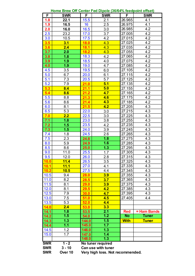
I decided to sweep the completed antenna through the entire frequency range, all the way to 2m (148mhz), although the balun is only rated to 50Mhz (6m). Final phone band SWR readings were 80m/1.8, 60m/8.5, 40m/1.6, 30m/11.1, 20m/1.5, 17m/4.3, 15m/4.6, 12m/1.6, 11m/4.3, 10m/3.9, 6m/4.4 (lower half) to 1.7 (upper half), 2m/1.5. I included the 11m band for any CB operators out there, although the SWR is too high for a CB without a tuner. (Further trimming/testing might achieve a lower SWR on some bands.)
Since the antenna read a low SWR on 2 meters, I gave it a quick test with my 2m HT and a VHF SWR meter. The antenna does work on 2m across the entire band and gets a signal out, although I suspect the balun is more of a radiating dummy load at that frequency rather than the antenna actually radiating. In an emergency though, it’s nice to know the antenna can be used on 2m for local work.
This makes the antenna usable on 5+ bands without a tuner. Due to the heavy duty balun, the other bands can also be used with a tuner, although the losses will go up. The LMR400 equivalent (or any low loss coax) will help to minimize the higher SWR power losses on the “not so resonant” bands. Most internal radio tuners can adjust for an SWR up to about 3. Above that you will have to use an external tuner. There is more on SWR at the end of the article.
Time For The Real Test
I connected my radio to the antenna and listened. To my surprise, there was very little noise and static compared to the old vertical I had in the Golden Horde EBT Empire (big city). I was also amazed at how many stations I heard on all bands that I never heard on my old vertical. I had been missing out on a lot of communications with my old, factory-made vertical, always believing that that’s as good as it got. Not!
After hearing someone calling CQ on 20m, I answered and received an instant reply with good signal reports. He was in Alabama. I was running 20 watts out on my portable radio. 1650 miles, with 20 watts is not bad!
In the six months that have gone by since the initial installation and testing above, I have made several contacts to South America and Australia on 20 meters, and multiple contacts between local and ~2600 miles, including Oregon, Wyoming, Canada, and southern and eastern states on the other bands. All made with 20 watts and good signal reports. This antenna definitely works!
I also received numerous short wave stations from many parts of the world, as well as several U.S. clear channel AM stations. Even though the antenna is low to the ground, with the center at 26’ (almost NVIS), it still appears to have good long range capabilities, even at the lower frequencies.
Lessons Learned
There were several things I learned from this project, including the following:
- Functional antennas are easy to build.
- You don’t have to spend mega $$$ to get a good antenna that works.
- The cost of the mast and coax (my only purchased components) was less than many of the commercially-made OCF antennas found on the web.
- The final antenna was almost two feet longer than the formula calculation (468/MHz). Definitely cut your initial wire 5% longer than determined by the formula. (468 divided by the lowest frequency in megahertz.)
- You can scale the antenna down to 40m on the lowest band or upsize it to have 160m as the lowest band. The offset percentages remain the same.
- A good antenna analyzer makes adjusting the antenna much easier than using a radio and SWR meter. An antenna analyzer is the ultimate tool for experimenting with antennas.
- You don’t have to use a manufactured mast. Trees, lumber, bamboo, rope, old utility poles, pipe, chimneys, or other objects will work, as long as it gets the antenna up in the air.
- By making your own antenna, you will know how to repair it, if it ever breaks. Being made of wire, any repairs will be easy. In a pinch, wires can be tied in a knot to splice them. For SHTF communications, stay away from complicated things and keep it simple (KISS). If you can’t use it or repair it when you need it, why have it.
- When it’s all done and tested, write down all final wire dimensions. This makes it easier if you ever have to make repairs and don’t have access to test equipment.
- The pressure treated end supports (brown) and light blue wire blend in with the surrounding environment and are almost invisible. Try to use colors or paint that blend in with your surroundings.
- This is an excellent antenna if you have to use coax and can’t use parallel line and a tuner. With the performance I have seen, this antenna is definitely a keeper.
A Final Note on SWR
I get many questions regarding SWR. Everyone has their opinion and thinks they are right. There is not enough space on this page to explain that subject in detail. Simply stated, at less than 100 watts, an SWR of 2 or less is okay for most radios without a tuner. However, always trim your antenna for the lowest SWR first! A SWR higher than 2, directly connected to most radios will cause the radios protective circuit to reduce power. Cheap radios without protection may be damaged.
An SWR up to 4-5 is okay with a tuner, with little loss of performance if you use low loss coax. Over 5 is also okay with a tuner, as long as you are willing to accept the increasing power loss and keep the transmitter power low. High SWR becomes critical if you are operating at high power. The higher the power, the higher the voltage on the coax, even in a perfectly matched system. That’s ohms law. “Force feeding” a high SWR, coax fed system with a tuner can create very high voltages, heat, potential arcing, and stress components like the balun, coax, and tuner. Running 500+ watts through a tuner into a coax fed system with an SWR of 15 will most likely arc in the connectors or turn your tuner, amplifier, or balun into a toaster. That is why balanced wire tuner outputs or end fed wire tuners have long ceramic insulators on the output terminals and don’t use coax. The voltages on these terminals can go over several 1000 volts or higher. (Parallel, ladder, or open wire line can handle these voltages and have low loss.) For an excellent article on SWR and coax, go to the ARRL.org web site and search the archives for “Understanding SWR by Example” in the November 2006 QST magazine. Remember, if you can hear them and they can hear you, you are doing okay!